
Process circuit — 200 m³/h
Specify inlet air, target outlet humidity/dew point and process-duct resistance. Obtain selected airflow and outlet conditions for that actual arrangement.
Read the source HVAC & REFRIGERATION
A compact published rotor unit with separate 200 m³/h process and 70 m³/h regeneration air paths; select it by moisture duty and duct conditions.
From Meizisenmei (Suzhou) Electric Co., Ltd. (MESEM)
Individual product research · HVACDeck Editorial · Sources checked 2026-10-11
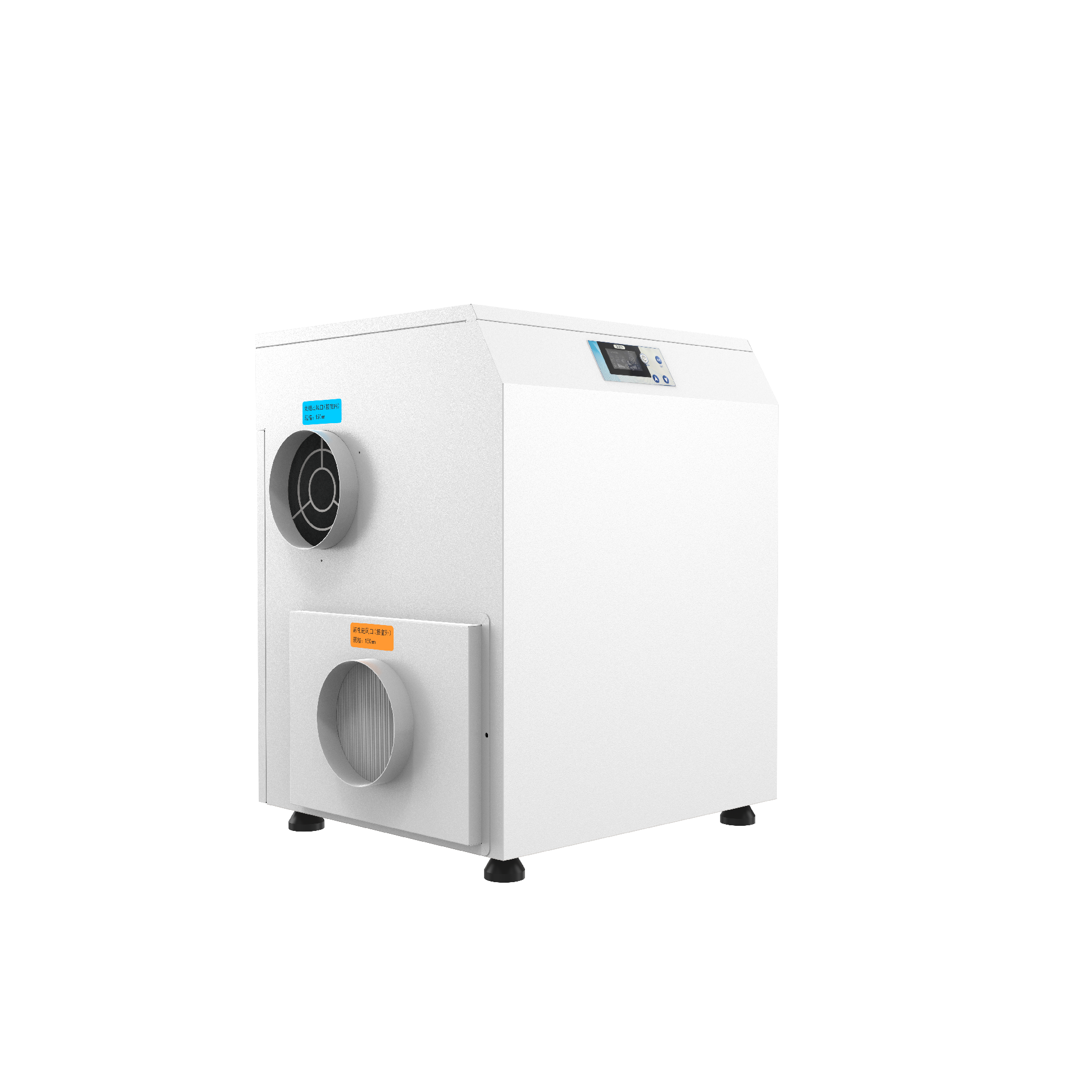
The official MESEM detail identifies ZLHK200D as a standalone rotor dehumidifier in its deep-dehumidification catalogue. It lists 200 m³/h process airflow, 70 m³/h regeneration airflow and 1.2 kg/h moisture removal. The table does not attach inlet temperature/humidity or an outlet dew-point target to that removal figure, so it cannot be treated as guaranteed capacity for every laboratory, storage room or low-temperature space.
The source page’s browser title still refers to an unrelated business-consulting template. This review follows the visible model heading and specification table, not that title. The table supplies installed component powers, supply voltage, weight and dimensions, but no duct-pressure curve, humidity-control accuracy or regeneration operating-temperature schedule.
The main practical question is whether the selected configuration can meet the moisture balance at the required inlet and outlet conditions while both air circuits are properly connected. A daily-litres or floor-area label from a marketplace is not a substitute for that selection.
The inspected source image shows a compact cabinet with a top control panel and two visible circular ports. It does not show all port labels, the full air-path diagram or a legible electrical nameplate; those details require the selected unit’s drawings.
The catalogue identifies a model reference; confirm the current revision and selected options.
Swipe the table, or focus it and use arrow keys, to read the conditions and sources.
| Parameter | Published value | Conditions and evidence |
|---|---|---|
| Process airflow | 200 m³/h | Published process stream; available external static pressure and selected inlet conditions are not supplied. Source |
| Regeneration airflow | 70 m³/h | Separate regeneration stream, not additional dry-air delivery to the room. Source |
| Moisture removal | 1.2 kg/h | Manufacturer table without attached inlet-air/test conditions; project performance remains to be selected. Source |
| Installed electrical power | 2.65 kW; regeneration heater 2 kW | Installed ratings, not measured continuous consumption or a seasonal energy figure. Source |
| Published supply | 220 V | Frequency, phase/connection details and current/protection schedule require confirmation. Source |
| Size and mass | 600 × 400 × 680 mm; 34 kg | Overall-size and machine-weight entries; no port/support/maintenance-clearance drawing supplied. Source |
The two airflow entries describe different jobs. The process stream is the air being dried; regeneration removes moisture from the rotor so it can continue drying. The 70 m³/h regeneration figure should not be added to the 200 m³/h process figure to advertise 270 m³/h of useful dry supply.
Before placement, request a marked diagram identifying every inlet/outlet, airflow direction and connection size. Confirm whether the process circuit is recirculated or treats outside air in the intended installation, and how regeneration air is supplied and exhausted. The reviewed page does not define those site connections or permissible duct resistance.
Specify inlet air, target outlet humidity/dew point and process-duct resistance. Obtain selected airflow and outlet conditions for that actual arrangement.
Read the sourceConfirm regeneration supply conditions, heater/control sequence, exhaust route and duct requirements. Keep moisture-laden exhaust away from the process inlet.
Read the sourceThe published 1.2 kg/h has no stated test temperature or humidity. Converting it into an arbitrary room size or assuming the same output in a cold, very dry inlet would hide the most important selection variables. Nor does the page specify a minimum attainable dew point or continuous outlet humidity.
Describe moisture generation in the process, outside-air infiltration, door opening, occupied/production hours and the initial drying requirement. Provide process inlet temperature/humidity and the actual target at the point of use. Ask for a selection schedule that states the removal rate, outlet conditions and airflow at that duty. If a room’s moisture load exceeds the selected output, changing the humidity-controller setpoint alone will not establish compliance with the target.
The source lists regeneration heating 2 kW, geared motor 0.1 kW, regeneration motor 0.2 kW and process fan 0.35 kW. Their sum matches the stated 2.65 kW installed power. That is an arithmetic check on the table, not evidence that the unit draws 2.65 kW continuously or that all components share one operating schedule.
For the order, request the wiring/current schedule, supply frequency/connection details, heater control and protection requirements. Obtain the expected operating sequence and any available energy measurements at the selected duty. The page does not give starting current, humidity-control precision, communication protocol or a remote-integration interface. Do not infer them from the model suffix or a different MESEM family.
2 + 0.1 + 0.2 + 0.35 = 2.65 kW from the four listed components; the calculation only checks the stated total.
Read the sourceConfirm actual current/protection, operating sequence, sensor/control scope and integration requirements with the chosen configuration.
The 600 × 400 × 680 mm dimensions and 34 kg weight are useful for an initial location check. They do not show support loads, port positions, service panels, rotor/filter access or installation clearances. No fan pressure curve or acceptable process/regeneration duct length was supplied.
Send the proposed layout and duct resistance for both circuits. Request the actual mounting/port drawing and service-access requirements, and confirm filter and rotor-maintenance instructions. For a clean or controlled environment, establish the requested filtration/material/cleanability criteria separately; the source’s application wording is not proof of a cleanliness classification or special-use approval.
The reviewed detail does not supply a model-specific performance report, certificate set, operating envelope or fixed warranty duration. A design patent for another MESEM dehumidifier and broad corporate manufacturing claims do not establish ZLHK200D performance.
Agree how the system will be checked after installation: the actual inlet conditions, both airflows, outlet humidity/dew point, selected control setpoint and relevant process/room target. Record the measurement method and agreed acceptance conditions in the order. A room humidity result and the unit outlet result answer different questions if infiltration and local moisture sources remain significant.
The published model is a starting point; a quoted configuration should identify included duct adapters, filters, humidity sensor/control and any auxiliary equipment rather than assuming they are all standard.
Provide inlet air conditions, target outlet/room humidity or dew point, process moisture load, infiltration and operating schedule.
Provide process and regeneration layouts, available utility supply, duct resistance, exhaust route and installation/service constraints.
Obtain duty-specific results, drawings, electrical/control schedule, included accessories, maintenance instructions and written warranty/acceptance terms.
Compiled by HVACDeck Editorial. Source review identifies what the publication states; it is not an independent performance test or certification.
Editorial method and corrections · Report a detail with this page URL
Send the manufacturer your required duty, installation conditions and the unresolved items identified in this brief.