


Basic constant-flow unit
Mechanical pressure compensation and a locally set flow; no external drive power described for regulation.
Read the source HVAC & REFRIGERATION
A pressure-independent mechanical regulator within a published operating range, with optional powered resetting; match the size, straight duct and control option to one scheduled airflow.
From Shanghai Huifeng HVAC Equipment Co., Ltd.
Individual product research · HVACDeck Editorial · Sources checked 2026-10-11
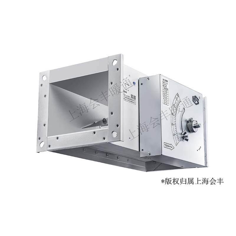
Huifeng’s HF-CAV/E item contains two actual technical sheets. They describe a mechanically balanced regulator with a moving restrictor, air bag, spring blade and cam. The regulator needs no external power to maintain its set flow within the permitted pressure-difference range. An optional actuator changes the setting; that is separate from the basic pressure-compensation mechanism.
The sheets provide useful size-specific flow ranges and installation allowances, but no complete acoustic schedule, quantified flow accuracy or independent test report. The stated conformity to JG/T436-2014 is the supplier’s claim, not a separately verified certification. Use the published values to prepare a selection, then obtain the exact selected assembly and factory setting.
This is an equipment family; its range does not identify one orderable configuration.
Swipe the table, or focus it and use arrow keys, to read the conditions and sources.
| Parameter | Published value | Conditions and evidence |
|---|---|---|
| Recommended pressure difference | 50–1000 Pa | Supplier sheet operating range; not the fan pressure or duct pressure class. Source |
| Working temperature | 10–50°C | Published regulator range; not a fire/smoke rating. Source |
| 160 × 100 mm example | 115–460 m³/h; minimum total pressure drop 50 Pa | One actual table row; not the entire family range. Source |
| 630 × 630 mm example | 3393–13572 m³/h; minimum total pressure drop 50 Pa | Separate actual size row; do not combine its flow with the smaller size. Source |
| Straight duct allowance | At least 1.5W inlet and 1W outlet | Sheet defines W as damper width; include in the actual installation layout. Source |
| Setting range | 4:1 | Published range; exact selected setpoint and accuracy still require confirmation. Source |
The sheet’s diagram explains how airflow inflates an air bag and creates closing torque on the restrictor, opposed by a spring blade acting through a cam. This describes the pressure-compensation principle; it does not supply a tested response time or flow-error curve. The external calibrated dial sets the required flow, with normal units factory-set according to standard flow unless a design value is agreed.
For remote resetting or variable settings, the sheet specifies optional analogue actuators using 0–10 VDC or 2–10 VDC. It separately mentions switching actuators for multi-state operation. Obtain the actual actuator, supply, signal interpretation, fail position and minimum/maximum settings. Do not treat a powered option as proof that the basic mechanical regulator needs an electrical supply.
Mechanical pressure compensation and a locally set flow; no external drive power described for regulation.
Read the sourceOptional actuator with 0–10 or 2–10 VDC control as specified; exact electrical schedule required.
Read the sourceSeparate multi-state control option; agree positions and the actual actuator rather than assume analogue control.
Read the sourceFor the 160 × 100 mm row, the published range is 115–460 m³/h. For 300 × 300 mm it is 850–3400 m³/h; for 630 × 630 mm it is 3393–13572 m³/h. Each row lists a minimum total pressure drop of 50 Pa. These are distinct size selections, not one regulator operating from 115 to 13572 m³/h.
Specify the actual supply or extract airflow, expected upstream/downstream conditions and available pressure across the regulator under all relevant operating modes. Ask how accuracy varies at the selected setting and over the agreed pressure range. Reserve the regulator loss in the fan/system calculation. The recommended 1000 Pa upper differential is not a blanket acceptable operating pressure for every surrounding component or an acoustic guarantee.
The sheet requests at least 1.5 times damper width W of straight inlet duct and one W at the outlet. A 300 mm-wide selection therefore calls for at least 450 mm inlet and 300 mm outlet straight lengths on this published basis. Coordinate nearby bends, transitions and branches with the supplier if those lengths cannot be provided.
The dimension table for 300 × 300 lists A/B 365/365 and C/D 335/335 mm; use the drawing to distinguish nominal opening, flange dimensions and casing arrangement. The illustrated axial length is 400 mm with a roughly 50 mm side projection. Obtain a selected dimensioned drawing, especially for actuator, silencer or reheating options, and leave access to the setting dial, fasteners and replaceable parts.
The illustrated ordering code distinguishes EN airflow regulator from END with a silencer, P1 surface coating from the standard galvanised steel specification, and no reheating coil from a two-row option. Confirm these choices individually: no silencer attenuation, coating performance or reheating duty follows from the option name alone.
The sheet says heights over 320 need two or more actuators. Check the proposed height and selected actuator quantity/coordination on the order drawing, rather than extrapolate a single motor from a smaller unit. Request any added dimensions, coil water-side duty, pressure loss and service access when the corresponding options are included. An optional reheat coil needs a separate selected thermal schedule.
The sheet names hospitals, laboratories and hotels as applications needing constant supply or extract. It does not establish containment, room pressure, leakage class, hygiene qualification or an accepted laboratory safety system. Agree the application requirements with the responsible designer and request applicable exact-assembly evidence.
Obtain tested flow tolerance, sound data at the selected flow/pressure and any relevant leakage or construction test. For a quiet room, compare the actual sound basis and attenuation of the selected variant rather than rely on the mechanical principle. The supplier’s statement about national-authority testing and JG/T436-2014 needs the original dated report, model coverage and applicable results before it is treated as independently established.
Actual operating window, size/flow rows, construction and order-code sheets are available.
Read the sourceA full original test report, numerical flow tolerance, acoustics and application-specific qualification were not recovered from this item.
Read the sourceAgree price, delivery and service separately; none is established in the technical sheets. Use the actual variant, nominal size, selected flow, pressure window and option schedule as the common quotation basis.
Issue supply/extract direction, required set flow and pressure range, temperature, straight-duct layout, access and control/options.
Approve the selected drawing, setting/accuracy evidence and any actuator, silencer or coil documents; check orientation and clearances.
Measure flow and regulator pressure conditions using the agreed method, record the dial/factory setting and control option, and investigate operation outside the approved window.
Compiled by HVACDeck Editorial. Source review identifies what the publication states; it is not an independent performance test or certification.
Editorial method and corrections · Report a detail with this page URL
Send the manufacturer your required duty, installation conditions and the unresolved items identified in this brief.