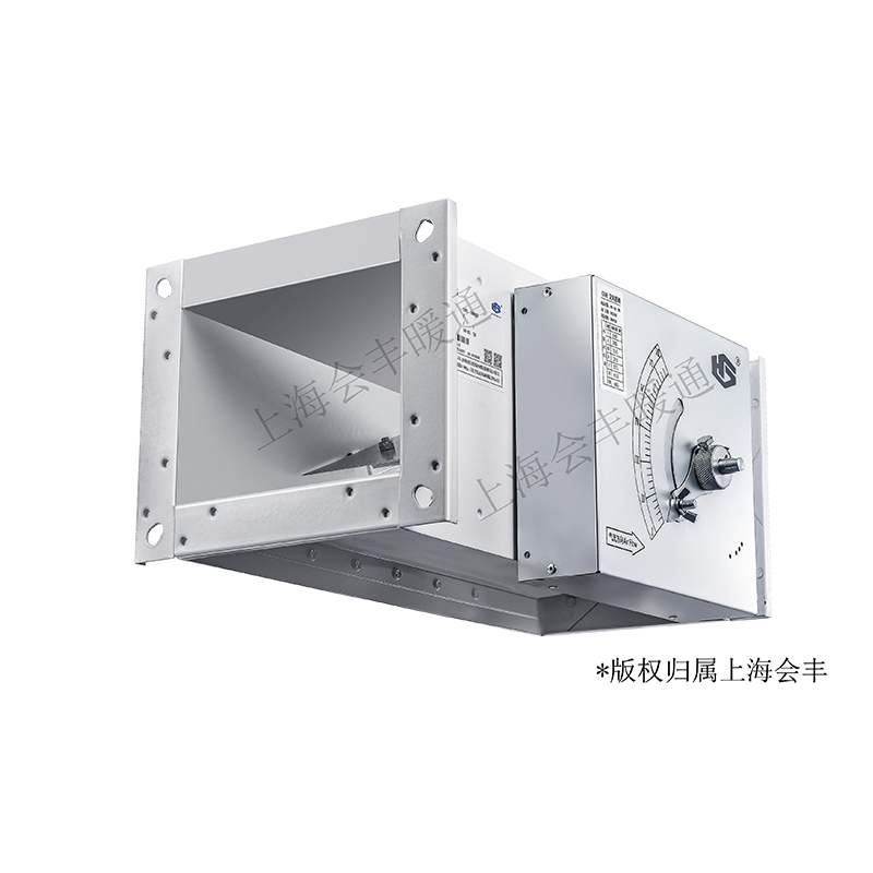
Mechanical constant-volume dampers, VAV controls and fan-powered terminals: distinguish the control method before selecting the duct size and interface.
1 published equipment referenceLatest source review 2026-10-07
01 / COMPANY
What this manufacturer offers
Shanghai Huifeng HVAC Equipment Co., Ltd. specialises in airflow-control equipment for central air-conditioning systems. Its official introduction separates constant-air-volume dampers, variable-air-volume dampers, VAV boxes and series/parallel fan-powered terminals. It also lists laboratory control products and supporting air outlets, valves and silencers. The published address is No. 1399 Muhua Road, Zhelin Town, Fengxian, Shanghai.
The HF-CAV/E publication contains substantial technical information inside images. Its mechanical regulator uses an airbag and spring arrangement to move a limiting plate as pressure changes. The manufacturer describes regulation without an external power supply and gives recommended pressure and temperature conditions. These details distinguish the base mechanical device from an electrically commanded airflow terminal.
The same publication includes an ordering diagram, dimensional schedule and straight-duct guidance. They are useful for defining an enquiry, although the lower airflow-parameter portion of the second image did not finish loading during review. No missing size-specific flow values or accuracy figures have been reconstructed.
Recommended differential pressure
50–1000 PaManufacturer's HF-CAV/E image; not a measured project duty or maximum system pressure. Source
Published working temperature
10–50°CConditions stated for the reviewed mechanical damper; other terminal families are not covered by this value. Source
Flow adjustment ratio
4:1Published ratio, not an absolute airflow range for every listed size. A size-specific selection is still required. Source
Example from the dimensional image
W×H 300×200; A 365, B 265, C 335, D 235Exact displayed row. The visible table does not print a unit; use the current dimensioned drawing to confirm units and tolerances. Source
Straight-duct guidance
Inlet 1.5W; outlet 1WSupplier guidance in the ordering image; W is stated as damper width. Confirm the selected installation and nearby fittings. Source
Swipe the table, or focus it and use arrow keys, to read conditions and sources.
Manufacturer-published information · HF-CAV/E
Parameter
Published value
Conditions and evidence
Recommended pressure difference
50–1000 Pa
Supplier sheet operating range; not the fan pressure or duct pressure class. Source
Working temperature
10–50°C
Published regulator range; not a fire/smoke rating. Source
160 × 100 mm example
115–460 m³/h; minimum total pressure drop 50 Pa
One actual table row; not the entire family range. Source
630 × 630 mm example
3393–13572 m³/h; minimum total pressure drop 50 Pa
Separate actual size row; do not combine its flow with the smaller size. Source
Straight duct allowance
At least 1.5W inlet and 1W outlet
Sheet defines W as damper width; include in the actual installation layout. Source
Setting range
4:1
Published range; exact selected setpoint and accuracy still require confirmation. Source
03 / PROJECT REVIEW
Huifeng: the mechanism behind a constant-air-volume selection
Three terminal arrangements with different control duties
Huifeng's product range covers distinct ways of controlling delivered air. Selecting the company first does not remove the need to specify the room operating strategy and terminal arrangement. (Sources 1 and 2.)
Mechanical CAV: hold a set flow
The HF-CAV/E limiting plate responds to the opposing airbag and spring forces. An external scale sets the requested flow; the source describes holding it within an allowed error as pressure changes. No numerical tolerance is visible in the reviewed material.
The introduction describes changing airflow to regulate room temperature and names integrated controllers, actuators and sensors. State the minimum/maximum airflow and exact selected control package; a mechanical CAV label does not establish this functionality.
Huifeng lists both series and parallel fan-powered terminals. Identify which arrangement is required and obtain its own fan, electrical and acoustic selection. The HF-CAV/E pressure range is not a rating for these separate terminal products.
Read the ordering diagram before specifying accessories
The source illustrates HF-CAV/EN-P1-0 / W×H / 2Nm as an ordering example. Its legend distinguishes the standard regulator EN from END with a silencer. P1 denotes a surface-coating option; the accompanying text describes galvanised steel sheet as the standard specification. The reheat-coil option is marked 0 for none and 2 for two rows. These are ordering choices, not evidence that every supplied damper includes coating, silencing or reheating. (Source 2.)
The actuator section is omitted when no actuator is selected. The notes distinguish analogue actuation for remote flow reset or multiple flow states, with 0–10 VDC or 2–10 VDC signals, from switching actuation for two-state control. The 2Nm entry is part of the illustrated ordering code rather than a universal motor requirement.
The text says regulators are normally preset before delivery and that an actuator-equipped model has maximum and minimum flows set. It also states that height above 320 requires two or more actuators. Confirm the height unit, actual actuator quantity and complete order code against a current selected drawing; the visible note does not supply an explicit unit for that threshold.
Size, access and duct approach belong in the same selection
The structure image lists W×H sizes from 160×100 through several rectangular sizes to 630×630, with A, B, C and D dimensions and a diagram showing their locations. For example, the 300×200 row reads A365/B265/C335/D235, while 630×630 reads A695/B695/C665/D665. The image also shows a 400 dimension along the damper body. The visible schedule does not state units, dimensional tolerances or a complete flow value for those examples. (Source 3.)
Do not choose solely from the duct opening. Leave access to the adjustment scale and any actuator or silencer selected in the ordering code. The supplier recommends inlet straight length of 1.5 times W and outlet straight length of W. Ask how an elbow, transition or branch close to the regulator affects the proposed installation.
The image's lower section is labelled airflow parameters, but that portion did not fully render in this review. The independently readable dimensional rows are retained; airflow values from the unread portion are not invented. Request the current complete selection sheet linking the exact size, setpoint, pressure range, accuracy and sound basis.
A control-brand list is not a compatibility matrix
The introduction names Siemens, Honeywell and Belimo control equipment and discusses conventional, DDC and MP-Bus arrangements. It also prints protocol names as “LongWorks” and “BAcnet”. Those spellings have not been silently converted into evidence of compatibility with a particular building-management network. The selected actuator, controller, sensor, signal and gateway need their own document references. (Source 1.)
Huifeng associates an MP-Bus optimisation system with energy savings up to 50%. The reviewed introduction gives no baseline, load profile, test report or project measurement supporting that percentage. It is a manufacturer marketing claim, not an expected saving from the mechanical HF-CAV/E damper. The listed hospital, pharmaceutical, shipbuilding and office references likewise remain supplier-listed project references; independent project acceptance was not verified.
The standard record and the factory's test claim have separate scopes
The HF-CAV/E technical image says it has been tested by a national authoritative body and meets JG/T 436-2014. No report number, testing organisation, model coverage or dated result is reproduced in the readable material. That statement is recorded as a supplier claim. (Source 2.)
The National Public Service Platform for Standards independently identifies JG/T 436-2014 as the recommended construction-industry standard 建筑通风风量调节阀, issued on 12 June 2014 and implemented on 1 December 2014. Its reviewed record marks the standard current. This establishes the identity and recorded status of the standard; it does not establish that Huifeng's particular order has passed a test. (Source 4.)
For a project requiring documented conformity, obtain the actual report and check the tested construction, size range and conditions against the proposed unit. The authoritative-platform company search did not establish a separate matched enterprise certification record for this profile. The standard listing is therefore not presented as a factory certificate.
07 / TRANSPARENCY
Sources and review scope
Compiled by HVACDeck Editorial. Page review: 2026-10-07. Publications are attributed below; their statements are not independent measurements by this platform.
HF-CAV/E dimensional image — source 3Checked 2026-10-07 · Visible dimensional schedule and diagram visually reviewed. No explicit table unit; lower airflow section failed to finish loading, so its values are not cited.