

Pipe connection
Match thread type, unions, orientation, dimensions and rated system pressure to the actual assembly. DN25 on a photo is not a complete connection drawing.
 HVAC & REFRIGERATION
A mechanical flow-control valve for heating and fan-coil branches: select the actual flow range and available differential pressure, then record the setting and verification.
From Shanxi Jiangong Shenhua HVAC Equipment Co., Ltd.
Individual product research · HVACDeck Editorial · Sources checked 2026-10-11
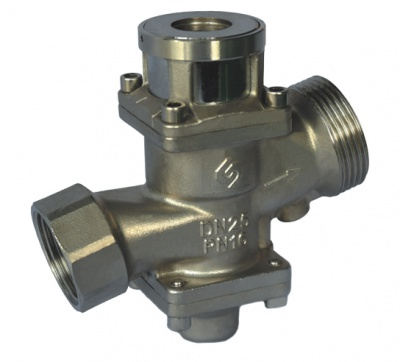
Jiangong Shenhua’s household valve publication describes a self-operated regulator with a precision-cast 304 stainless-steel body/bonnet and a planar ceramic regulating plate. Its three original images show the body, a numbered flow-setting dial and a removable restricted-adjustment tool. The body photograph is visibly marked DN25 and PN16, with a cast flow arrow. Those are markings on the photographed example, not a complete offered-size schedule or a pressure test certificate.
The published constant-flow differential-pressure window is 0.02–0.3 MPa. It is distinct from the PN marking. The page supplies no size-by-size flow table or curve for selecting a household branch. Use the stated features to prepare a technical enquiry, while specifying the actual flow, temperature, system pressure and water conditions that the quoted valve must handle.
This is an equipment family; its range does not identify one orderable configuration.
Swipe the table, or focus it and use arrow keys, to read the conditions and sources.
| Parameter | Published value | Conditions and evidence |
|---|---|---|
| Published operating differential pressure | 0.02–0.3 MPa | Constant-flow operating statement; not maximum body pressure or a selected flow curve. Source |
| Published accuracy statements | Scale indication ±5%; constant flow ±6% | Separate supplier statements; no reproduced method, specimen or test conditions. Source |
| Setting dial | 170° adjustment scale | Photograph shows a numbered dial; size-specific setting-to-flow schedule is required. Source |
| Body and bonnet | Precision-cast 304 stainless steel | Supplier description; other components stated as stainless steel or brass, with no complete wetted schedule. Source |
| Photographed body markings | DN25 · PN16 · flow-direction arrow | Read on the actual original image only; not proof all offered sizes have this designation or a current conformity certificate. Source |
| Stated cycle test | 100,000 on/off operations | Manufacturer attributes test to a national air-conditioning institute; original report/date/specimen absent. Source |
For a heating branch, determine the design thermal load and intended water temperature drop with the project designer. The flow requirement follows that heat balance; the valve connection should not be the only selection input. For a fan-coil branch, use the actual selected coil duty, water temperatures and permissible hydraulic resistance.
Ask for the model/size flow range, setting-to-flow schedule and curve across differential pressure. State whether the target is fixed design flow, a permitted reduced setting or a control sequence involving another valve. The household publication describes mechanical adjustment and a restricted lock. It does not establish a modulating electrical actuator or building-management interface; the neighbouring electric product is a separate item.
Match thread type, unions, orientation, dimensions and rated system pressure to the actual assembly. DN25 on a photo is not a complete connection drawing.
Match required branch flow to the quoted model’s minimum/maximum setting and verified characteristic, rather than assigning litres per hour from the dial photograph.
Check available differential pressure at that branch under the relevant system operating modes, separately from maximum static pressure.
The published differential-pressure range corresponds to 20–300 kPa across the valve. A system pump pressure or an upstream gauge reading alone does not establish this local difference. Consider the remote branch at design demand and near branches as other circuits close or change demand; the installed regulator needs a valid operating point in each relevant condition.
The supplier says neighbouring adjustments do not disturb the given flow. That statement still requires the quoted flow to remain inside the selected valve’s verified regulation envelope. Below the necessary differential pressure, no guaranteed constant-flow behaviour is established here. Above the documented upper limit, request the approved treatment rather than assume the valve is a pressure-reducing or surge-protection device. There is no published noise or cavitation curve for this household model.
The original dial image has a numbered flow scale and the page states ±5% indication accuracy. A marked setting is useful for repeatable commissioning, but it is not a continuous, independently measured branch-flow result. Record the actual valve designation and size with the dial position and the supplier’s corresponding flow schedule.
The photograph of the restricted tool demonstrates an adjustment arrangement; it does not prove resistance to every form of tampering. Agree who has adjustment authority and how changes are logged. The temperature connection is described for return-water measurement. A return temperature alone cannot establish branch flow or delivered heat; use a defined verification method with the necessary measurements.
The manufacturer describes a ceramic sealing/regulating plate and a zero-contact anti-sticking plug design. Its claim of operation in poor water conditions contains no quantified solids, chemistry or filtration limits. Obtain the full wetted-material and seal schedule, maximum/minimum operating temperatures and permitted treatment/fluid composition for the chosen model.
Plan flushing, debris removal, strainer provision where specified and accessible isolation/service arrangements with the installer. Do not derive a universal maintenance-free promise or zero-leakage guarantee from the construction description. The page also mentions water-supply use, but gives no potable-water material approval. Such an application needs the relevant evidence before this heating-oriented valve is selected.
The 100,000-operation statement supplies no report number, test date, exact valve specimen or conditions. Ask for the original report if the procurement specification relies on it, and match size, materials, pressure, temperature and test sequence to the offered product. A cycle count cannot be converted into years of installation service or a warranty period.
Similarly, the ±6% constant-flow claim requires its own defined flow/pressure test basis. The PN16 marking on one photographed body is not an inspection report or proof of performance through the whole published differential-pressure range. Request relevant pressure/leakage and flow-regulation records separately; avoid treating one certificate as evidence of all three properties.
Identifiable construction, mechanical setting features, example body markings and three explicit supplier performance statements.
Read the sourceExact model/size and connections, setting curve, temperature/fluid limits and reports tied to the proposed construction.
A constant-flow device is one part of the hydronic circuit. Define isolation, measurement access, pump/control responsibility and the acceptance tolerance with the project team. The supplier’s promise of balancing and energy saving is not a measured outcome for a specific building.
Record design branch flow, available valve differential pressure, exact model/size, flow setting, system pressure/temperature and fluid conditions.
Follow the supplied orientation and connection instructions; flush/protect the circuit, establish the operating condition and verify branch flow using the agreed method.
Record dial position, verification result and conditions, adjustment responsibility, servicing instructions and any required recheck after system changes.
Compiled by HVACDeck Editorial. Source review identifies what the publication states; it is not an independent performance test or certification.
Editorial method and corrections · Report a detail with this page URL
Send the manufacturer your required duty, installation conditions and the unresolved items identified in this brief.

