
Header connection
Choose the required 1-inch or 1¼-inch option and confirm the actual connection drawing, thread designation, gender and sealing arrangement. Do not select by photograph.
Read the source HVAC & REFRIGERATION
An identified 2–12-way manifold with published connection details: verify the branch adapters, actuator package and hydraulic selection before ordering.
From Zhejiang Sunfly HVAC Intelligent Control Co., Ltd.
Individual product research · HVACDeck Editorial · Sources checked 2026-10-11
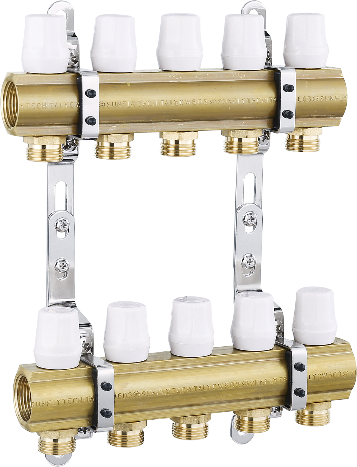
Sunfly’s English product page identifies XF20160H as a manifold and publishes a CW603N brass specification, 2–12 ways, 50 mm branch spacing and two nominal header sizes. It is a component for distributing and collecting water circuits; the listing does not describe a complete pump/mixing/control package.
The original photo shows a pair of brass headers on brackets with white valve caps and a five-branch example. Five branches in that image do not limit the published 2–12-way range or establish what is included in every order. No branch flowmeters or installed electrical actuators were established from that photo.
A useful selection therefore begins with the required circuit count, pipe and connection schedule, design flows and control arrangement. The published pressure and temperature limits need a supplier-confirmed operating envelope, not an assumption that both limits apply simultaneously.
The catalogue identifies a model reference; confirm the current revision and selected options.
Swipe the table, or focus it and use arrow keys, to read the conditions and sources.
| Parameter | Published value | Conditions and evidence |
|---|---|---|
| Model | XF20160H | Exact identifier on the English catalogue page. Confirm current revision and ordered configuration. Source |
| Declared body material | CW603N brass | The page describes Italian-imported brass; origin, batch composition and application suitability not independently verified. Source |
| Published nominal pressure | ≤10 bar | Listing limit; no pressure-temperature derating or test method supplied. Source |
| Published working temperature | ≤100°C | Listing limit; simultaneous operation at 10 bar/100°C not established. Source |
| Outlet count and spacing | 2–12 ways; 50 mm branch spacing | Order the required number of circuits; obtain the matching dimensional drawing. Source |
| Header size options | 1 inch / 1¼ inch | Published size string interpreted as alternatives; thread gender and port assignment require a drawing. Source |
| Branch connections | 3/4 inch × 16; 3/4 inch × 20 | Catalogue notation. Confirm adapter, pipe material/wall size and supplied connection parts. Source |
| Actuator interface | M30 × 1.5 | Mechanical thread only; voltage, stroke, force and control compatibility not specified. Source |
| Connection thread reference | ISO 228 | Manufacturer statement; exact thread designation, seal and mating connection must be specified. Source |
The public range is 2–12 ways, while the reviewed image illustrates five outlets on each of two headers. The photo helps identify the arrangement but does not provide a bill of materials. The page does not establish that isolation valves, air vents, drain/fill fittings, flowmeters, actuators or a cabinet are included.
Give the supplier a circuit schedule and ask for a configuration drawing and itemised package. Include spare positions only where the design calls for them. Obtain the total width, depth, mounting pitch, header orientation and space needed for adapter/actuator installation; 50 mm branch spacing alone cannot size the enclosure.
The header options and branch notation refer to different interfaces. An order can have the right circuit count and still be incompatible with the system’s pipe or mating fittings.
Choose the required 1-inch or 1¼-inch option and confirm the actual connection drawing, thread designation, gender and sealing arrangement. Do not select by photograph.
Read the sourceResolve whether the branch package is the published 3/4-inch × 16 or × 20 arrangement, which pipe dimensions/materials it supports and whether the adapters/inserts/seals are included.
Read the sourceThe listing publishes an M30 × 1.5 actuator connection thread but no actuator model, electrical rating, stroke, force, opening direction or fail position. A matching thread does not settle valve travel or controls. The white caps in the catalogue image are not evidence of a powered actuator supplied with the order.
Ask for the compatible valve/actuator pairing, operating voltage, signal and controller wiring, travel and behavior without power. If a zone-control package is offered, request its separately identified components and documentation. Preserve manual access and commissioning instructions in the delivered package.
No flow/pressure-drop curve or Kv schedule was established from the page. Without those data, header size and outlet count cannot demonstrate that the selected manifold will deliver the project’s design flow. Similarly, the CW603N label does not establish suitability for every water chemistry or treatment mixture.
Provide circuit design flows and available differential pressure. Request pressure-drop/Kv data for the configured manifold and valves, plus the intended balancing method.
Request the pressure-temperature schedule, seal materials, permitted medium and any water-treatment/additive restrictions. The page’s hot/cold-water wording is not approval for any glycol concentration.
Where the order requires it, obtain body/seal material declarations, batch traceability and inspection records tied to the supplied configuration. Italian-origin wording remains a manufacturer claim until substantiated.
The national standards platform identifies GB/T 29730-2025, Distribution manifold of cold/hot water, as current, implemented on 1 February 2026 and replacing GB/T 29730-2013. It lists 浙江鑫帆暖通智控股份有限公司 among the drafting organisations. This demonstrates a named contribution to the standard, not certification or a pass result for XF20160H.
If the purchase specification uses that standard, request the supplier’s stated applicable edition and configuration-specific conformity/test evidence. This review read the official status and authorship record; it does not claim to have checked every technical clause or a complete XF20160H test report. Export or other project requirements must be specified separately.
Request the approved installation and commissioning instructions for the selected assembly, including orientation, connection/seal method, flushing, filling, venting, leak/pressure checks and balancing. This page is not a substitute for those instructions and provides no tightening torque or test-pressure procedure.
Approve circuit count, header/branch interfaces, dimensions, included parts, controls and pressure-temperature envelope.
Reconcile delivered labels and parts with the drawing; obtain current instructions and clarify the installer’s responsibilities for piping and controls.
Record the selected settings, circuit labels, commissioning results and spare-part references; agree warranty and service terms for the actual destination.
Compiled by HVACDeck Editorial. Source review identifies what the publication states; it is not an independent performance test or certification.
Editorial method and corrections · Report a detail with this page URL
Send the manufacturer your required duty, installation conditions and the unresolved items identified in this brief.