


Original tooling evidence
Diameter-specific tube matrices, fin choices and end-plate details.
 HVAC & REFRIGERATION
Original geometry options support an OEM enquiry; they do not supply a rated refrigerant circuit, pressure approval or interchangeable coil.
From Beijing Sunjet · Custom fin-and-tube heat exchangers
Individual product research · HVACDeck Editorial · Sources checked 2026-10-11
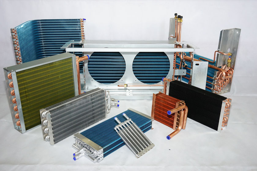
Sunjet’s custom fin-and-tube offer is supported by four original tooling sheets rather than a rated model catalogue. The drawings cover 7/7.94, 9.52, 12.7 and 15.88 mm tube options with specific tube matrices, fin shapes/spacing and end-plate details. A product montage shows several coil constructions but provides no selected refrigerant/fluid, pressure rating or duty. The twelve numbered photo pages are therefore consolidated into one design-selection brief instead of invented model URLs.
For example, the 9.52 mm sheet includes a rectangular 25.4 × 25.4 mm tube matrix and 3.0–6.35 mm fin spacing, while the 15.88 mm rectangular 50 × 50 mm option lists 4.0–8.0 mm spacing. Neither geometry is a complete performance selection. Approve actual air/fluid conditions, circuit, material and allowable pressure loss together; tube size and fin spacing alone cannot establish heat duty, defrost suitability or a pressure-approved replacement coil.
This is an equipment family; its range does not identify one orderable configuration.
Swipe the table, or focus it and use arrow keys, to read the conditions and sources.
| Parameter | Published value | Conditions and evidence |
|---|---|---|
| Four source sheets | 7/7.94, 9.52, 12.7 and 15.88 mm tube options | Original drawings visually read; no one-page-per-diameter or numbered-photo padding. Source |
| 9.52 mm rectangular option | Tube matrix 25.4 × 25.4 mm; fin spacing 3.0–6.35 mm | One specific tooling option, not all 9.52 mm configurations. Source |
| 15.88 mm rectangular option | Tube matrix 50 × 50 mm; fin spacing 4.0–8.0 mm | One specific larger-tube option; source also offers other matrices. Source |
| 15.88 mm tube wall choices | Smooth copper φ15.88 × 0.5 or × 0.75 mm | Manufacturing choices, not a calculated or approved pressure rating. Source |
| Smaller-tube material scope | 7 mm sheet includes rifled/smooth copper and aluminium tube choices | Actual pattern/material combination requires order confirmation; not transferred to larger sheets. Source |
| Missing selected-duty file | No current capacity, air/fluid pressure loss, circuit/connection or design-pressure schedule | Obtain conditioned selection and approved drawing before purchase. Source |
Issue required duty with entering air dry/wet conditions, airflow and allowed air-side resistance, plus fluid/refrigerant temperatures, flow and pressure limits. Ask for the actual circuit and conditioned selection, not a nominal kW inferred from a photograph or tube diameter.
Define operating/upset conditions, condensate or defrost requirements where applicable and the connected system’s limits. The official sheets contain geometry, not an evaporator/condenser rating or suitability for every refrigerant. No performance map, freezing limit or approach temperature is invented here.
The 9.52 mm rectangular option and larger 15.88 mm rectangular option have different pitch/spacing references; each sheet also contains alternatives. Approve transverse/longitudinal pitch, rows, face dimensions, tube count and fin type together in the issued drawing. Shared tube diameter alone does not identify the tooling.
Select fin spacing and material against the actual air stream, moisture, cleaning and required pressure loss through supplier engineering. A wider spacing reference does not independently guarantee fouling resistance or an improved duty. Request the resulting thermal/air-side selection for the complete geometry.
The 15.88 mm sheet offers smooth copper with 0.5/0.75 mm wall choices. Obtain the selected design-pressure/temperature approval, material standard and joining/test procedure; do not calculate a public pressure rating from wall thickness alone. Smaller-sheet aluminium/rifled options are not a universal larger-tube BOM.
Close headers, circuit count, connections, end plates and corrosion requirements with the actual order. End-plate thickness choices do not establish mounting loads or chemical compatibility. Obtain fluid cleanliness, material traceability and pressure/leak-test records for the approved circuit.
Supply mounting, connection orientation, air direction and service/cleaning constraints, including an existing approved drawing if this is a replacement. The original montage shows multiple shapes and coatings without identifying current model numbers or included attachments. Do not assign fabricated model names to the numbered pages.
Obtain complete current dimensions, tolerances, circuit and installation instructions before tooling or manufacture. A similar photographed outline or same tube size does not make two coils interchangeable. Resolve material/coating and mounting responsibility explicitly.
Approve the conditioned selection, current drawing and material/circuit BOM, then agree dimensional, cleanliness, pressure/leak and any required thermal checks. Identify the evidence needed for exact component/conformity requirements rather than adopting an unreadable historical UL image as approval.
Current price, delivery and independently verified heat-duty or pressure results remain unknown. This one custom-family brief uses the original geometry to prepare a detailed enquiry while preserving the distinction between tooling options and a tested specification.
Diameter-specific tube matrices, fin choices and end-plate details.
Conditioned duty, fluid/refrigerant circuit, pressure and actual drawing.
Material traceability, dimensions, cleanliness and defined test records.
Compiled by HVACDeck Editorial. Source review identifies what the publication states; it is not an independent performance test or certification.
Editorial method and corrections · Report a detail with this page URL
Send the manufacturer your required duty, installation conditions and the unresolved items identified in this brief.
