


Water-side selection
Actual fluid chemistry, temperatures, flow, permissible pressure loss and freeze/condensation requirements.
 HVAC & REFRIGERATION
Custom air-heating/cooling assemblies: distinguish catalogue construction choices from the actual hot-water, steam or oil selection and its pressure, temperature and cleaning requirements.
From Shanghai Yuanhe HVAC Equipment Manufacturing Co., Ltd.
Individual product research · HVACDeck Editorial · Sources checked 2026-10-11
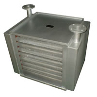
Yuanhe’s radiator page includes seven assembly/application photographs and a technical construction graphic. The graphic describes heating or cooling air for heating, cooling, dehumidification and drying, with construction choices in tube, fin and casing materials, circuiting and row count. It names hot oil, steam and cooling water as possible media. These are different service selections, not one interchangeable rated coil.
The graphic prints family-level maximum-use claims of 14 kilograms per square centimetre and 230°C, but supplies no selected model, material/wall-thickness schedule, design code or proof that both maxima apply together. Its photos have no readable selected thermal rating. Use the actual medium, conditions and construction to obtain an approved calculation and drawing, retaining the scope of those catalogue claims.
This is an equipment family; its range does not identify one orderable configuration.
Swipe the table, or focus it and use arrow keys, to read the conditions and sources.
| Parameter | Published value | Conditions and evidence |
|---|---|---|
| Services named | Air heating/cooling, dehumidification and drying | Actual application graphic; selected air process and medium must be specified. Source |
| Published maximum-use claims | 14 kilograms/cm² and 230°C | Original wording retained without an assumed pressure conversion; family claims are not a simultaneous selected rating. Source |
| Tube outside-diameter line | 16–89 mm | Published construction range in the graphic; not an order drawing or wall-thickness schedule. Source |
| Row choices illustrated | 1, 2, 3, 4, 5, 6, 8, 10, 12 … | Catalogue configuration choices; no capacity is inferred from row count. Source |
| Materials listed | Copper, stainless, carbon-steel and aluminium choices | Different tube/fin/casing schedules; no universal fluid compatibility. Source |
| Process evidence | Tube insertion/expansion, welding, water/nitrogen operations and drying | Actual separate process image; no test pressure/duration/result documented. Source |
For hot or cooling water, issue actual inlet/outlet temperatures, fluid composition and flow or required heat duty, with permissible water-side pressure loss. Include glycol type/concentration where used. For steam, specify actual steam conditions and condensate/back-pressure requirements with the responsible designer. For oil, provide its actual temperature-dependent properties and viscosity.
On the air side, state airflow, entering temperature and moisture, required leaving condition, heat duty and permissible pressure loss. Dehumidification needs a sensible/latent and condensation basis; drying needs the actual air process and contaminants. The catalogue’s application names do not establish a duty, drying time, hygienic qualification or utility consumption.
Actual fluid chemistry, temperatures, flow, permissible pressure loss and freeze/condensation requirements.
Exact medium properties and pressure/state, plus the relevant condensate or circulation arrangement; separate material/mechanical approval.
Airflow, entering/leaving air state, thermal duty, resistance and moisture/contamination conditions.
Do not interpret the graphic’s maximum-use statements as a pressure test, design-code approval or guaranteed simultaneous operating point. Require the supplier to state the selected design and operating pressures/temperatures, the pressure unit and basis, material grades, tube wall thickness, joint construction and applicable requirements. Obtain the actual test method and record for the ordered assembly.
The same graphic lists several tube materials and connecting arrangements. Match the selected medium and its chemistry to the exact wetted tube/header/connection schedule rather than assume every material is suitable up to the family maxima. Resolve corrosion and cleaning-agent compatibility on the service basis. A photograph of flanged headers does not establish their pressure class.
The radiator graphic describes tube outside diameters from 16 to 89 mm, custom circuiting and several row counts. A separate fin image illustrates nine forms, including straight, windowed, ripple, raised-edge flat, sine-wave, single-direction wave, flat and opened forms. Its diameter/spacing strings do not provide a complete selected dimension legend.
Require fin material/thickness, pitch and form, tube diameter/wall, face dimensions, rows, circuits and selected air/fluid pressure losses. More rows or a visually dense fin pack are not automatically a better selection: coordinate thermal duty, available fan pressure and cleaning access. The stated option to make forms in sheet copper does not prove that a pictured radiator contains copper fins. Confirm each actual material separately.
The seven photographed applications include chemical work, laundry drying, food machinery, hotel accommodation/bathrooms and drying rooms. The photos show different header and frame arrangements but no model identification, food-contact approval or accepted project record. For the actual application, define dirt/fibre loading, moisture and cleaning method, then agree a maintainable fin spacing and surface/material treatment.
Provide a dimensioned installation envelope, airflow direction, connection positions, support loads and a route to remove or clean the assembly. Coordinate vent/drain provisions with the actual circuit and installation orientation; the graphic calls them standard or custom but gives no universal arrangement. Where cooling can condense moisture, specify collection/drainage and access as part of the installed system rather than assume every radiator includes a drain pan.
The process graphic illustrates formed fins, tube insertion and expansion, welded tube/header joints, water testing, nitrogen detection and degreasing/drying. These named stages support questions about the manufacturing route; they do not establish test pressure, hold time, leak sensitivity, acceptance criteria or a passed batch record.
For the selected assembly, agree material traceability, joint/process requirements, dimensional inspection and pressure/leakage evidence with a record tied to its identification. The image’s nitrogen operation is not a safe field-test instruction. Any test should follow the applicable approved procedure and be performed by competent personnel. Neither the machine gallery nor these process illustrations verify annual capacity or an independently audited quality system.
The radiator and fin graphics supply configuration choices and examples, not a selected performance schedule.
Read the sourceWater/nitrogen and finish stages are named; acceptance criteria and ordered-unit results remain required.
Read the sourceNo exact price, lead time, warranty or thermal selection is supplied by the reviewed radiator page. Compare offers against one defined medium and air process, with the same mechanical limits, materials, dimensions and acceptance basis.
Provide both air and medium conditions, duty, allowable losses, chemistry, contaminants, available space and cleaning needs.
Review thermal/hydraulic calculation, tube/fin/casing schedule, circuit/dimension drawing, operating limits and agreed test criteria.
Match identification, materials and manufacturing/test records; verify the agreed thermal and flow conditions and keep cleaning/service instructions.
Compiled by HVACDeck Editorial. Source review identifies what the publication states; it is not an independent performance test or certification.
Editorial method and corrections · Report a detail with this page URL
Send the manufacturer your required duty, installation conditions and the unresolved items identified in this brief.
