


DBF40 with A-type fan
4,000 m³/h at listed 373 Pa; motor 0.8 kW × 1, 930 rpm; listed 60 dB(A), 180 kg reference weight.
Read the source HVAC & REFRIGERATION
Original tables distinguish direct-drive and belt arrangements; match airflow, pressure basis and the complete orientation code before ordering.
From Zhejiang Annaite Ventilator Manufacture Co., Ltd.
Individual product research · HVACDeck Editorial · Sources checked 2026-10-11
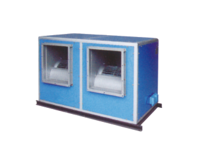
The official detail combines DBF ordinary ventilation with a modified DSF smoke-extraction version. Its actual image tables supply useful DBF examples, but drive arrangement and the selected table row change pressure, motor power, noise and weight at the same nominal airflow.
The model-code image explains a 40 designation as 4,000 m³/h, A as direct transmission and E as belt transmission. Additional codes describe filter/shaft arrangement and numbered air-port position. These are needed to define a physical cabinet; “DBF40” alone leaves important choices unresolved.
The source also contains two inconsistencies relevant to ordering: the code diagram maps Y to the right-side shaft, while an E-table example calls Y left-side; the table header uses residual pressure while that example calls a 700 Pa entry total pressure. Both need a confirmed drawing/selection rather than an editorial guess.
This is an equipment family; its range does not identify one orderable configuration.
Swipe the table, or focus it and use arrow keys, to read the conditions and sources.
| Parameter | Published value | Conditions and evidence |
|---|---|---|
| A-type DBF40 table example | 4,000 m³/h · 373 Pa · 0.8 kW × 1 | A-fan table; 930 rpm, listed noise 60 dB(A), reference weight 180 kg. Not a complete fan curve or installed acoustic guarantee. Source |
| E-type DBF40 row a example | 4,000 m³/h · 330 Pa · 0.75 kW | E-fan table row a; listed cabinet noise 66 dB(A), reference weight 280 kg. Pressure terminology needs confirmation. Source |
| E-type DBF40 row b example | 4,000 m³/h · 495 Pa · 1.1 kW | E-fan table row b; listed noise 68 dB(A), reference weight 290 kg. Different selection from row a. Source |
| Published port arrangements | 12 numbered inlet/outlet arrangements | Original diagram; actual order still requires a signed orientation/access drawing. Source |
For DBF40 the A-fan table lists 4,000 m³/h, 373 Pa, 0.8 kW × one motor, 930 rpm, 60 dB(A) and a reference weight of 180 kg. At the same 4,000 m³/h, E-table DBF40 rows a/b/c list respectively 330/495/680 Pa, 0.75/1.1/2.2 kW, 66/68/70 dB(A) and 280/290/300 kg. These are different listed selections, not interchangeable maximum values.
Choose the duty before the drive/motor row and request its fan curve and operating limits. The table does not state rated air density, measurement arrangement or a guaranteed acoustic result in the buyer’s room. Motor rating is not measured electrical consumption at every operating condition.
4,000 m³/h at listed 373 Pa; motor 0.8 kW × 1, 930 rpm; listed 60 dB(A), 180 kg reference weight.
Read the source4,000 m³/h at listed 330 Pa; 0.75 kW motor; listed 66 dB(A), 280 kg reference weight.
Read the source4,000 m³/h at listed 680 Pa; 2.2 kW motor; listed 70 dB(A), 300 kg reference weight.
Read the sourceThe E-table header labels its Pa column as residual pressure. The printed DBF80EaY2 example below it describes 8,000 m³/h, 700 Pa and 3 kW, calling the pressure total pressure. The row-a values themselves agree with the 700 Pa/3 kW entry, but the pressure terminology differs. This review retains the discrepancy rather than treating both descriptions as an external-static-pressure guarantee.
Have the supplier define whether the selected figure is total, static or available pressure at the agreed boundary, and state what cabinet/filter losses are included. Give the actual duct and accessory resistance, with filter condition and silencers identified. Obtain a selected-duty schedule/curve using the same pressure definition as the project calculation.
The original diagram numbers twelve inlet/outlet arrangements, including upper/lower discharge and side-inlet alternatives. The code image illustrates DBF–40–A–Y–2 and maps Z/Y/M/N to left/right/top/bottom shaft arrangements, with the inlet-facing viewpoint stated. The E-table worked example instead calls Y the left-side arrangement.
Do not reverse a cabinet or select maintenance access by relying on the letter alone. Send a plan/elevation marking airflow arrows, inlet-facing viewpoint, shaft/motor/filter side, chosen numbered arrangement and access space. Ask the supplier to resolve the Y wording and confirm the actual approved drawing revision.
40 means 4,000 m³/h; A direct and E belt transmission; Y is shown as right-side shaft in the diagram.
Read the sourceDBF80EaY2 text calls Y left-side and 700 Pa total pressure, while the table header says residual pressure. No editorial correction assumed.
Read the sourceTwelve numbered arrangements support layout discussion; they do not replace selected cabinet dimensions/access approval.
Read the sourceThe written construction describes galvanised impeller/casing, a detachable cold-formed metal frame, coloured outer panels, an inner microperforated galvanised acoustic layer and fine glass-wool infill. An aluminium-alloy frame is optional. It permits suspended or floor-mounted installation and site assembly/disassembly.
Request the selected panel specification, fan/motor access, inspection opening and frame/support arrangement. For a suspended installation, confirm weight, lifting and structural-support requirements on the actual drawing rather than using a reference table weight as the installed load. For a belt arrangement, include the space and procedure for drive inspection/tensioning. Listed dB(A) values have no reviewed measurement distance or spectral data, so request the acoustic information needed for the building design.
The source states that the modified DSF uses high-temperature structural panels and places the motor/transmission outside the cabinet, claiming operation above 280°C for more than 100 minutes. This is supplier wording for that version; no exact-configuration test report establishing it was reviewed. It is not assigned to normal DBF.
If the enquiry is for smoke extraction, identify the required duty, exact assembly, motor/drive/control arrangement and applicable conformity/test documentation for the destination. Inspected fire-gallery attachments concern dampers, the energy-efficiency report cover concerns SWF-13, and the explosion document concerns BDWEX-900. They cannot certify this DBF or a proposed DSF variant.
The table images show performance examples but no complete dimensional schedule for the selected cabinet was established in the reviewed entry. Electrical supply, starting/control method and accessory inclusions also require an order-specific offer. The supplier’s twelve-month-from-dispatch warranty and fault/geographic exclusions should be confirmed in the written order.
Supply airflow, clearly defined pressure/resistance, air conditions, electrical supply and acoustic objective; select the exact A/E row with its curve.
Resolve Y/shaft wording, port number and viewpoint; obtain dimensions, maintenance access, cabinet materials, weight and support/lifting details.
Agree performance/acoustic test conditions and boundaries, configuration-specific documents, accessory scope, dispatch-based warranty and destination support.
Compiled by HVACDeck Editorial. Source review identifies what the publication states; it is not an independent performance test or certification.
Editorial method and corrections · Report a detail with this page URL
Send the manufacturer your required duty, installation conditions and the unresolved items identified in this brief.
