


Pressure and impeller
Choose axial I/II or mixed-flow III/IV against required airflow/total pressure and space, rather than choosing from pipe diameter alone.
 HVAC & REFRIGERATION
Use the full original catalogue: axial and mixed-flow forms, single and two-speed tables, roof and silenced arrangements, and exact certificate scope.
From Shaoxing Shangyu Dashun Ventilation Equipment Co., Ltd.
Individual product research · HVACDeck Editorial · Sources checked 2026-10-11
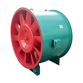
Dashun’s HTF product page is almost entirely an image catalogue. All 17 original sheets were read for this product review. They provide explanations, separate I–IV/D airflow–total-pressure schedules, installation drawings, roof and silenced arrangements, and wiring/maintenance notes. The family heading alone would hide most of the selection information.
The catalogue defines I/II as axial single/two-speed forms and III/IV as mixed-flow single/two-speed forms. D is a low-pressure form, W a roof arrangement and X a silenced arrangement. The separately reviewed certificate image names HTF-I-16A and four suffix variants, rather than the entire HTF catalogue. Match the technical selection and applicable current evidence to the exact ordered designation.
This is an equipment family; its range does not identify one orderable configuration.
Swipe the table, or focus it and use arrow keys, to read the conditions and sources.
| Parameter | Published value | Conditions and evidence |
|---|---|---|
| I/II arrangement | Axial impeller · I single-speed / II two-speed | Definitions in the original explanation sheet; not transferable to another supplier’s HTFC codes. Source |
| III/IV arrangement | Mixed-flow impeller · III single-speed / IV two-speed | Separate performance and dimension schedules in the original catalogue. Source |
| HTF-I No.3.5 example | 6,122 m³/h at 205 Pa total; 2,900 r/min; 1.1 kW | One paired recommended point and motor entry. Same size also lists 3,500 m³/h at 552 Pa; no mixing maxima. Source |
| HTF-II No.5 two-mode example | High: 9,824 m³/h at 510 Pa; low: 4,912 m³/h at 127 Pa | First recommended rows at 2,900/1,450 r/min; published installed motor entry 3/2.5 kW. Actual project selection still required. Source |
| HTF-I/II No.3.5 dimensional example | L 520 mm; D1 360 mm; D2 390 mm; D3 430 mm | Drawing references only, with flange-hole pattern explicitly advisory and ordinarily undrilled. Source |
| Original certificate identity | Z2024081814003216 · HTF-I-16A main type | Image names Shaoxing Shangyu Dashun; includes HTF-I-16B/C/D/E. Does not cover every catalogue variant. Source |
| Printed certificate dates | 8 November 2024–7 November 2029 | Original manufacturer-hosted certificate image read. Issuer website attempt timed out; current status not independently verified. Source |
The catalogue’s normal-pressure group I/II uses an axial impeller; its medium-pressure III/IV group uses mixed flow. The Roman numerals also distinguish single and two-speed motors within those groups. They are not four interchangeable names for the same impeller and duty.
D has its own low-pressure table. W refers to roof installation with a selected cap, and the roof sheet states that corresponding I–IV/D forms can be supplied in that arrangement. X1/X2 have distinct silencing constructions. Ask for the complete configuration and approved selection, including the catalogue’s naming of GYF as a comparable product family; do not silently relabel a GYF quotation as the exact certified HTF designation.
Choose axial I/II or mixed-flow III/IV against required airflow/total pressure and space, rather than choosing from pipe diameter alone.
Choose a documented normal/emergency schedule. Each speed requires a paired point and motor/control basis.
Agree W cap and roof interface or X1/X2 attenuation construction with the full dimensional and performance selection.
The HTF-I No.3.5 table gives five recommended points. Its 6,122 m³/h at 205 Pa and 3,500 m³/h at 552 Pa values describe different points at 2,900 r/min. They do not support 6,122 m³/h at 552 Pa. The column is total pressure, unlike a static-pressure catalogue.
The HTF-II No.5 table separately lists 2,900 and 1,450 r/min schedules. Its first high/low rows are 9,824 m³/h at 510 Pa and 4,912 m³/h at 127 Pa. These examples illustrate how to read the table; they are not a selection for the buyer’s duct network. Require a marked curve with actual air conditions, resistance and motor loading for each mode. The catalogue uses “standard conditions” without a complete reproduced density definition; confirm that basis and any correction with the supplier.
The original explanation says operation for more than 60 minutes at 300°C and separately 20 hours per run at 100°C. It cites an older 1999 test-standard reference and national inspection wording. These are supplier catalogue assertions, not a complete temperature/duration report for every variant and accessory configuration.
The actual original certificate identifies an axial smoke-exhaust product, HTF-I-16A as the unit/main type, with HTF-I-16B, 16C, 16D and 16E included. It cites XF 211-2009 and a 2019 certification rule, with printed dates 2024-11-08 to 2029-11-07. The official issuer-site attempt failed to produce a readable status result. Ask for a verifiable current record and full report, including the offered size/speed, motor and applicable extensions, before relying on it for an order. A named size-16 certificate does not by itself certify No.3.5 or a mixed-flow IV fan.
Certificate number, named holder, five HTF-I-16 suffixes and printed validity are visible in the actual image.
Read the sourceNo current issuer-status result or complete high-temperature test report is reproduced. Certification scope, test duty and project suitability require separate matching.
The I/II, III/IV and D sheets use different dimension tables. For the I/II No.3.5 example, L is 520 mm and D1/D2/D3 are 360/390/430 mm. Use the referenced sketch rather than treat all three diameters as one duct size. The note says flange drilling dimensions are reference-only and the manufacturer normally does not drill them; agree the mating flange and drilling before delivery.
The W roof sheet gives base, fan and cap dimensions and offers FRP or steel cap forms. Confirm the cap material, complete height, roof curb/support, weather detail and removal clearance with an approved drawing. A roof illustration is not a wind-load, weathering or building-interface approval. The normal I/II straight fan envelope should not be used as the complete roof assembly.
The X description distinguishes X1, with inlet/outlet silencers, from X2, with a silenced casing and inlet/outlet silencers. It quotes broad attenuation ranges for different silencer lengths, but gives no full octave-band selection or agreed installed measurement condition. Obtain frequency-dependent acoustic data and the actual added resistance before selecting the fan and attenuator together.
The performance tables list A-weighted levels without a full reproduced measurement method/distance. Do not turn them into an indoor boundary guarantee or subtract a broad attenuation range to promise a final room noise. Include duct-borne sound, casing breakout, vibration and the project receptor in the acoustic assessment. Corrosive, grease-laden or explosive service likewise needs an explicit material/protection selection; the general application list is not an approval for those media.
The final original sheet includes two-speed wiring diagrams and instructions to read the product manual, check current/three-phase supply, inspect abnormal operation and coordinate smoke outlet/fan interlocking. These catalogue diagrams should inform questions, not replace the current selected motor terminal diagram or the responsible electrical designer’s controls.
Record the full variant/number, normal and emergency airflow/total pressure, speed/motor data, media and required thermal duty.
Confirm flange drilling, supports/access, roof or silencer package, motor-specific wiring and the project’s smoke-control interlocks/changeover.
Check direction, speeds, airflow/pressure, current, vibration and interlock response at defined conditions; retain reports, settings and maintenance instructions.
Compiled by HVACDeck Editorial. Source review identifies what the publication states; it is not an independent performance test or certification.
Editorial method and corrections · Report a detail with this page URL
Send the manufacturer your required duty, installation conditions and the unresolved items identified in this brief.