
Inside the quoted package
Identify condenser, heat-rejection equipment, pump, tank, hydraulic module, controls and protection devices by the actual model’s bill of materials. Clarify pump duty, tank volume and access.
Read the source HVAC & REFRIGERATION
Published 150–1201.5 kW family at 12→7°C chilled water: verify the selected model, integrated package and local heat-rejection conditions.
From Takamura Guangdong Co., Ltd.
Individual product research · HVACDeck Editorial · Sources checked 2026-10-11
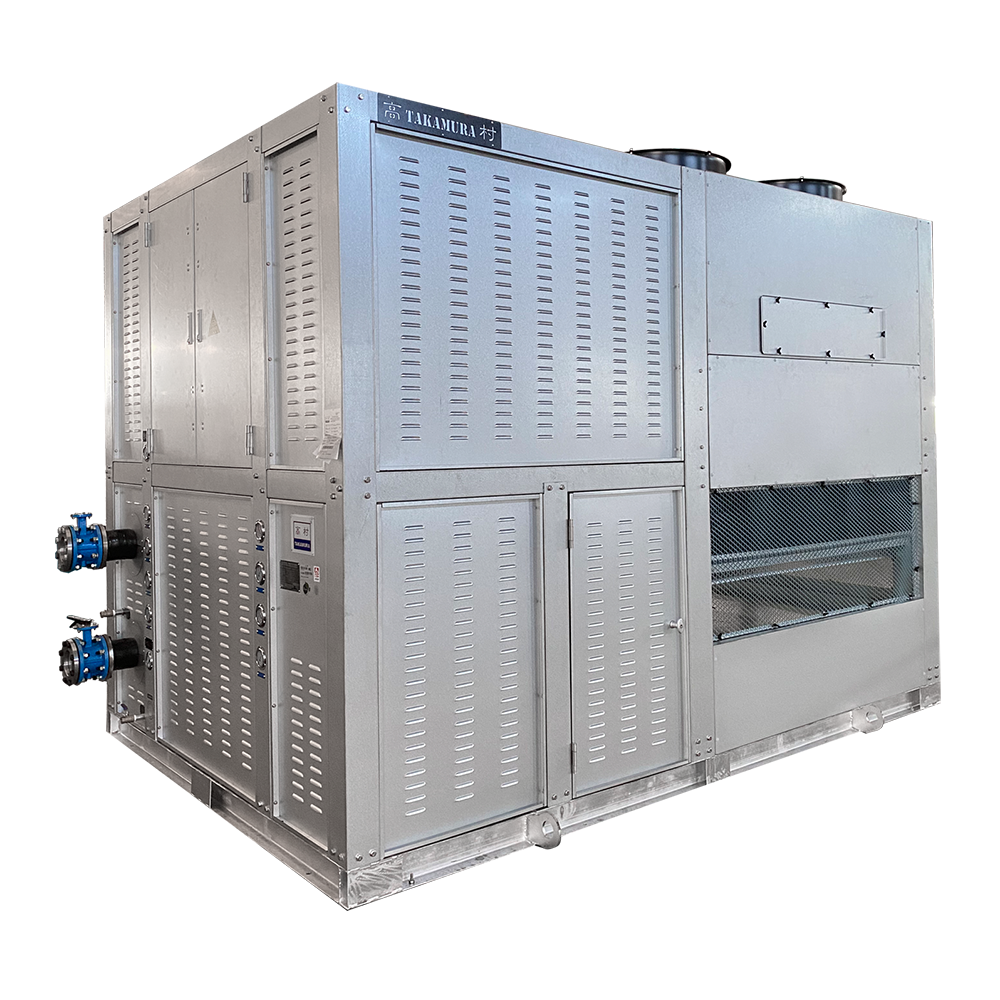
Takamura’s original TS-C-UNI page publishes cooling capacity of 150–1201.5 kW, water flow of 24–206 m³/h and chilled-water inlet/outlet temperature of 12→7°C. These are series ranges. The readable page does not map each capacity to a model and flow, or state the ambient wet-bulb condition and electrical input used for the ratings.
The description says the package combines evaporative cooling with mechanical refrigeration and integrates the condenser, cooling tower, water pump and tank. It also mentions a hydraulic module and several protection functions. Integration changes the supplied boundary; it does not remove the need to define water services, installation access, controls and maintenance.
The page says rooftop placement is possible and claims approximately 10% savings compared with conventional water-cooled equipment. Neither statement establishes suitability for every roof or a verified energy result at the buyer’s site. Use the published values as an enquiry starting point and obtain the selected model’s complete schedule.
This is an equipment family; its range does not identify one orderable configuration.
Swipe the table, or focus it and use arrow keys, to read the conditions and sources.
| Parameter | Published value | Conditions and evidence |
|---|---|---|
| Series identifier | TS-C-UNI | Original integrated evaporatively cooled listing. No individual suffix/model mapping established. Source |
| Published cooling range | 150–1201.5 kW | Series range with 12→7°C chilled-water statement; ambient rating conditions/input not published in readable detail. Source |
| Published water-flow range | 24–206 m³/h | Series range; endpoints are not treated as matched capacity/flow pairs. Obtain a model-specific schedule. Source |
| Chilled-water temperatures | 12°C inlet → 7°C outlet | Published family condition, not confirmation of every available operating temperature. Source |
| Declared integrated equipment | Condenser, cooling tower, pump and water tank | Manufacturer package description plus hydraulic module; exact parts and external services require a drawing. Source |
| Published protective functions | High/low pressure, discharge temperature, compressor overload, phase loss and water shortage | Manufacturer list; settings, sensors, circuit behavior and restart sequence not established. Source |
The largest published capacity is not a selection for a particular load. Request the proposed model, cooling output and input at the project’s design weather and water temperatures, together with flow, pressure drop and operating envelope. The 24–206 m³/h range must be matched through that model’s schedule rather than pairing the smallest or largest endpoints by assumption.
State whether the duty is process cooling or comfort HVAC, operating hours, load profile, permitted fluid composition and temperature precision. The page names food processing, data centres and pharmaceutical/biological applications, but those categories do not establish a specific process tolerance, hygiene design or redundancy.
The supplier describes an integrated condenser/tower/pump/tank arrangement. Ask for a boundary drawing showing the refrigeration, chilled-water and evaporative-water services, including what is factory assembled and what remains a site connection.
Identify condenser, heat-rejection equipment, pump, tank, hydraulic module, controls and protection devices by the actual model’s bill of materials. Clarify pump duty, tank volume and access.
Read the sourceDefine electrical feed, load-side piping, required water services/drainage, access and supervisory control. Confirm each interface from the supplier’s approved installation schedule.
Agree responsibility for distribution pumps or other external equipment, piping/valves, insulation, balancing and commissioning. Integration does not define all site works.
The product description claims roughly 10% lower energy use than traditional water-cooled equipment and a larger advantage over air-cooled equipment. The readable page does not identify comparison models, weather/load profile, measurement boundary or a full test report. This review therefore does not present the percentage as verified performance or a contractual saving.
Ask for full/part-load figures at shared conditions and state which pumps, fans and auxiliary loads are included. Where a project requires a savings commitment, agree a baseline, measurement/calculation method and operating period. Water consumption and service costs should also be specified separately; the public page supplies no numerical water-use schedule.
The catalogue says the equipment can be installed on a roof, but gives no structural load, dimensions, sound schedule, required clearance or airflow study. Obtain operating weight, support/anchoring details, lifting arrangement, service zones and drainage/connection requirements before placement. A generic location statement cannot approve a roof.
Ask the supplier to identify the design wet-bulb/weather conditions, winter operation and water-management requirements appropriate to the site. Request its approved treatment, cleaning, inspection and shutdown instructions. This brief does not supply a universal water-treatment recipe or installation procedure.
The source describes an “environmentally friendly refrigerant” without identifying the fluid. Do not substitute a refrigerant name from another product. Related entries include flooded, heat-pump, heat-recovery and variable-frequency screw equipment; those features are not established for TS-C-UNI merely because they appear nearby.
Request refrigerant and charge, compressor type/count, circuit arrangement, capacity control and permitted operating envelope for the quoted model.
Request pump duty, tank volume, flow/pressure-drop data, water quality requirements, supply/current/starting data and electrical protection.
Obtain the actual alarm/interlock settings, water-shortage sensing, restart behavior, BMS protocol/point list and versioned control/wiring documentation.
The official service page describes a 12-month quality period from the ex-factory date, free repair for qualifying quality problems excluding misuse, and continuing paid/support service thereafter. Its promise to handle a reported problem within 12 hours is not stated as a guaranteed on-site repair completion. Confirm the contract’s warranty start, commissioning delays and support at the actual destination.
Agree the model, rating conditions, interfaces, included equipment, limits and current installation/maintenance documents.
Define witnessed tests, measurement boundaries, control/protection checks and commissioning acceptance conditions; identify who supplies the evidence.
Confirm the destination’s service party, spare parts, water-management responsibilities, warranty timing and escalation procedure.
Read the sourceCompiled by HVACDeck Editorial. Source review identifies what the publication states; it is not an independent performance test or certification.
Editorial method and corrections · Report a detail with this page URL
Send the manufacturer your required duty, installation conditions and the unresolved items identified in this brief.