
Family envelope
Nominal sizes and independent airflow/total-pressure ranges.
 HVAC & REFRIGERATION
Choose a real operating point and motor arrangement inside the family envelope; maximum flow and pressure are not one rated duty.
From Yichang Qinye · Ventilation and duct manufacturing
Individual product research · HVACDeck Editorial · Sources checked 2026-10-11
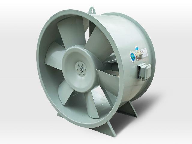
Qinye publishes SWF as a mixed-flow ventilation family with eighteen nominal sizes from 250 to 1,400 mm. Its stated family envelope is 500–110,000 m³/h airflow and 50–1,400 Pa total pressure. These are separate catalogue limits, not a curve or a guarantee that one fan delivers both maxima. The original images show cylindrical housings and mounting feet, but no readable selected model/rpm/power schedule.
The page distinguishes single-speed I and dual-speed II arrangements and discusses a variable-frequency motor/controller alternative, suggesting 25–50 Hz. It also makes unconditioned acoustic comparisons and cites a commissioned inspection without providing the actual result. Use this page to prepare a model-specific operating-point enquiry: required airflow, system resistance, sound target, motor/control compatibility and mounting. General ventilation data do not establish a certified smoke-extraction or explosion-protected configuration.
This is an equipment family; its range does not identify one orderable configuration.
Swipe the table, or focus it and use arrow keys, to read the conditions and sources.
| Parameter | Published value | Conditions and evidence |
|---|---|---|
| Published family size range | 250–1,400 mm; eighteen sizes | Nominal size range; no current individual model dimension schedule established. Source |
| Published airflow range | 500–110,000 m³/h | Family limits only; no selected speed/pressure operating-point curve. Source |
| Published total pressure range | 50–1,400 Pa | Not simultaneous with maximum airflow; static and total pressure must not be confused. Source |
| Speed arrangements | I single speed; II dual speed; VFD option described | Exact motor and drive compatibility requires ordered configuration confirmation. Source |
| Suggested VFD interval | 25–50 Hz | Supplier suggestion, not approval for every motor/application or emergency operation. Source |
| Acoustic and testing limit | Claimed 2–3 dB comparison; commissioned inspection mentioned | No full measurement conditions/current exact-model test results verified. Source |
Provide the required airflow at the actual duct resistance and state whether the selection pressure is static or total. Ask for the SWF model, rpm, blade arrangement, density basis and curve with the selected point marked. The two envelope maxima do not prove one fan can achieve that combined demand.
Include filters, dampers, silencers and the actual inlet/outlet arrangement in the project selection. Obtain absorbed power and motor margin at the relevant operating conditions rather than assuming that a compact cylindrical photo establishes efficiency or interchangeable performance.
For a single-speed fan, approve the fixed duty and resulting electrical schedule. For dual speed, request both operating curves, motor wiring and the actual switching sequence. The I/II terminology identifies arrangements rather than two universally interchangeable site modes.
If a VFD is proposed, get written motor/drive compatibility, allowed frequency range, control signals and protection requirements for the actual order. The supplier’s suggested 25–50 Hz interval is not a complete motor cooling, resonance or emergency-system approval. Confirm minimum ventilation and failure response with the responsible project engineer.
The description claims a relative 2–3 dB reduction and lower noise, but does not supply a selected-model sound spectrum, reference fan or full measurement setup. Do not publish an absolute noise level or claim that a silencer is unnecessary for the building.
Request sound power or defined sound-pressure measurements for the actual duty, with method, distance and installation assumptions. Evaluate the entire air path and receiver requirement, including breakout and terminal noise, through the project acoustics design rather than relying on a generic comparative claim.
The text offers horizontal or vertical duct connection, while the photographs show cylindrical housings and feet. Ask for the issued arrangement, supports, mass, loads, access and connection dimensions; the photo does not establish that every size may use either orientation without changes.
Confirm inlet/outlet clearances and guards, motor service access, isolation and maintenance instructions. A pictured nameplate is not sufficiently readable to assign a motor rating. None of these general-family statements supplies a smoke-temperature test result or hazardous-area approval for the ordered assembly.
The page names a commissioned inspection and references a technical standard, but the reviewed content does not include its complete results or current applicability to an ordered SWF. Request the full exact-model record and the applicable current specification from the supplier. Do not treat this as a certification of every size and speed.
Compare quotations only after flow/pressure, motor/control, sound evidence, mounting and delivery scope match. Current prices, stock and independently tested efficiency are unknown. This individually written brief separates real family boundaries from the additional selection and acceptance evidence.
Nominal sizes and independent airflow/total-pressure ranges.
Exact model/speed curve, power, sound and motor/control arrangement.
Current applicable documents, issued installation file and agreed tests.
Compiled by HVACDeck Editorial. Source review identifies what the publication states; it is not an independent performance test or certification.
Editorial method and corrections · Report a detail with this page URL
Send the manufacturer your required duty, installation conditions and the unresolved items identified in this brief.
Qinye dampers: thermal closure versus commanded smoke opening