
Grand LSS closed pure-water cooling systems
Focus on the protected equipment’s coolant quality, hydraulic circuit and interlocks; verify the secondary heat sink for the selected package.
From Wenling Grand · Industrial fluid-cooling systems
Individual product research · HVACDeck Editorial · Sources checked 2026-10-11

Specify an LSS loop around the actual power equipment
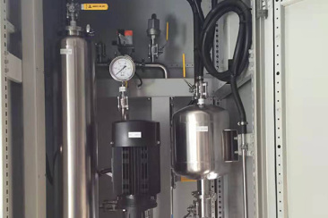
Grand describes LSS as a closed circulating pure-water cooling system for power rectifiers, medium/high-frequency supplies, water-cooled induction furnaces and high-power medium-voltage drives. Its published scope specifically includes control of coolant temperature, flow and water quality, with protection and communication functions. The original family photo shows a pump, vessel, pressure gauge and internal fluid piping; it does not identify an issued model or prove the full package contents.
The company overview identifies water-to-water cooling within its manufacturing portfolio, but the LSS page does not supply a model-specific heat-sink schematic or a quantitative operating schedule. Establish the selected primary/secondary arrangement, thermal duty and OEM coolant limits in the quotation rather than treating ‘pure water’ as a complete specification.
Published parameters and their scope
This is an equipment family; its range does not identify one orderable configuration.
- Family designation
- LSS
Swipe the table, or focus it and use arrow keys, to read the conditions and sources.
| Parameter | Published value | Conditions and evidence |
|---|---|---|
| Published protected loads | Rectifiers, induction-furnace equipment, medium/high-frequency supplies and medium-voltage drives | Official application description; no independently reviewed installed project list. Source |
| Stated functions | Coolant temperature, flow and water-quality control; protection and communication | Actual thresholds, sensors, protocol and control scope not published. Source |
| Circuit type | Closed circulating pure-water system | Official LSS wording; fluid recipe, treatment and makeup design must be issued. Source |
| Observed assembly detail | Pump, vessel, gauge and internal piping in the family photograph | Visual evidence only; no model, pump head or redundancy inferred. Source |
| Unclosed selection data | Heat duty, primary/secondary temperatures, flow, pressure drop and quality limits | No quantified current rating table provided on the inspected page. Source |
Selection and application review
Use the equipment OEM’s limits to define pure water
Obtain the rectifier, drive or furnace supplier’s approved fluid specification, wetted-material restrictions and minimum/maximum flow requirements. ‘Pure water’ alone does not define an acceptable conductivity, pH, treatment chemistry or contamination limit. Grand’s claim that the system addresses corrosion, scaling and blockage is not proof that any site makeup water will be suitable.
Require a written water-quality schedule, treatment train and maintenance procedure. Agree conductivity measurement location, calibration and alarm limits, filter service, sampling and consumable replacement. Avoid copying numerical coolant limits from an unrelated electrical machine or another supplier’s manual.
Close the primary circuit and the external heat sink separately
Provide the equipment heat losses, permissible inlet/return temperatures, pressure drop and all operating modes. Ask for the pump duty, flow-distribution drawing and P&ID, including which parts belong to Grand’s package and which remain with the protected equipment. Confirm the allowable system pressure and fill, vent and drain arrangements.
If the selected LSS package uses a water-to-water exchanger, specify site secondary-water temperature, flow, quality and pressure, plus isolation between circuits. The reviewed family page does not establish that every LSS has the same exchanger or can tolerate an arbitrary site-water temperature. Obtain a duty selection and package drawing for the actual order.
Tie protection signals to the rectifier, furnace or drive
List the cooling conditions under which the connected equipment may start, must derate or must stop. Obtain the supplier’s cause-and-effect schedule and agree ownership of each permissive/trip. The official page mentions protection and communication but does not publish a safety architecture, latency or register list.
Confirm hardwired versus network signals, sensor-failure behaviour, communication loss, pump fault and high-temperature/low-flow responses. Assess the planned interruption and restart sequence with the equipment OEM. A general control function is not evidence of uninterrupted cooling after power loss or a full redundant system.
Plan access for water treatment and fluid maintenance
The original photo exposes internal service components, so ask for the current enclosure and access drawing before installation. Identify clearance for pump removal, vessel service, strainers and treatment components. Determine how sampling, draining and maintenance can be performed without introducing incompatible water or debris into the protected circuit.
Request spares and consumables for the exact supplied parts, with storage and replenishment requirements. ‘Compact’ website wording does not settle the installed access envelope or the time allowed before a thermal shutdown. Define planned downtime and any bypass/standby arrangements in the order.
Accept an integrated cooling loop, not a marketing label
Prepare an enquiry containing the OEM coolant requirements, connected heat losses, hydraulic resistance, secondary utilities and control interfaces. Request the issued selection, component list, drawing revision and inspection/test plan.
Agree witnessed hydraulic and thermal checks at stated conditions, fluid-quality checks and simulated alarm/communication behaviour. Neither capacity, stock nor a delivered reliability level has been independently established. This product brief records the actual LSS scope and the decisions needed to make a technically comparable purchase; it does not substitute for the final engineering design.
Approve coolant limits
Obtain OEM requirements and issue the treatment/monitoring specification.
Define both fluid interfaces
Close protected-loop duty and external heat-sink conditions.
Test control responses
Agree flow/temperature/quality alarms, permissives and fault tests.
Sources and review scope
Compiled by HVACDeck Editorial. Source review identifies what the publication states; it is not an independent performance test or certification.
- Official Grand LSS family pageChecked 2026-10-11 · Complete description read and original internal-assembly photograph inspected; no current quantitative rating table.
- Official manufacturing overviewChecked 2026-10-11 · Water-water systems and dedicated testing described by the supplier; exact LSS package scope still requires issued drawings.
Editorial method and corrections · Report a detail with this page URL
Turn the evidence into an enquiry
Send the manufacturer your required duty, installation conditions and the unresolved items identified in this brief.
Continue the selection
Other equipment from this manufacturer
Grand LYF transformer oil/air coolers