
Envicool XStorm fan walls · Air load and cold-source integration
Select the remaining air-side load, water point and fan redundancy before using supplier energy or density comparisons.
From Shenzhen Envicool Technology Co., Ltd.
Individual product research · HVACDeck Editorial · Sources checked 2026-10-11

Match the fan wall to the data hall and its cold source
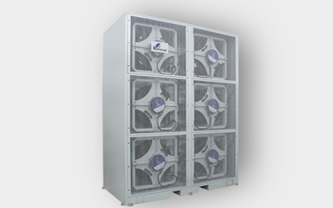
Envicool's XStorm fan wall is an air-side cooling offer for large or ultra-large data centres. Its official product page describes a large-area, low-resistance coil, uniform air distribution, several optional cold sources and operation with relatively high water temperature and large temperature difference. The original supplier illustration shows a vertical multi-fan assembly; it is a product rendering, not a photograph of an installed project or a rated capacity table. The page also describes combining air and liquid cooling with an adjustable air-to-liquid ratio.
Selection therefore starts with the remaining air-cooled IT load and the chosen cold-source/water interface. The webpage's CLF below 0.1, more-than-60% annual saving and increased capacity per width are supplier comparisons without an inspected baseline or project calculation. They are not adopted as guaranteed results for a buyer's data hall. This brief explains the actual air/water and hybrid-cooling decisions while keeping capacity, dimensions and acceptance data that need a selected quotation explicit.
Published parameters and their scope
This is an equipment family; its range does not identify one orderable configuration.
- Family designation
- XStorm fan-wall family
Swipe the table, or focus it and use arrow keys, to read the conditions and sources.
| Parameter | Published value | Conditions and evidence |
|---|---|---|
| Official application | Large or ultra-large data centres | Supplier product-page scope, not a specified capacity for every data hall. Source |
| Described coil/air approach | Large-area low-air-resistance coil and more uniform distribution | No inspected pressure-drop or uniformity test curve. Source |
| Cold-source options | Multiple cold sources; high-water-temperature/large-ΔT scenarios | Exact entering/leaving water point and selected rating not issued. Source |
| Hybrid cooling role | Air and liquid cooling with adjustable ratio | Project allocation must be selected; no fixed supported rack density inferred. Source |
| Efficiency comparisons | CLF <0.1; >60% annual saving; +60% capacity per width | Supplier claims with absent inspected baseline, weather/load profile and system boundary. Source |
| Missing selected schedule | Capacity, airflow, dimensions, water losses and fan/input data | No fabricated model rating or witnessed performance. Source |
Selection and application review
Separate total IT load from the fan-wall air duty
Define the IT heat load, rack layout, containment and the portion removed by liquid cooling. Ask the supplier to select the fan wall for the remaining air duty at the actual return and required supply conditions. An adjustable air/liquid ratio is an integration option, not a guarantee of one rack density or system size.
Confirm how air is distributed through the hall and what measurement points determine acceptance. The rendering's visible fan count is not assigned as the fixed fan count of every order, nor proof of redundancy. Get a selected assembly and airflow distribution assessment for the actual layout.
Choose the cold-source and water interface
The official page allows different cold sources and says the coil suits relatively high water temperature and large temperature difference. Issue the project's available water temperatures, flow/pressure boundary, fluid and required heat-removal point. Obtain the selected coil rating, water/air pressure drops and actual materials.
Identify the cold-source equipment and pumps provided separately versus included in the quote. The fan wall is not automatically a self-contained refrigeration machine. High-water-temperature language does not establish a universal free-cooling climate or permit replacing issued thermal selections with a maximum marketing number.
Define resilience and service access
Request the selected fan arrangement, controls, redundancy and behaviour after a fan or water-supply fault. Confirm monitoring interfaces and sensor positions on issued documents. The broad uniform-distribution statement is not evidence of acceptable flow during every failure state.
Obtain selected dimensions, structural/support scope, maintenance clearances and replacement access. Ask for sound and complete electrical input at the ordered duty. The source rendering supports product layout only; it does not provide mass, mounting ratings or an installed acoustic result.
Evaluate the energy claims with a project boundary
The supplier states CLF below 0.1, an annual saving above 60%, and increases in capacity per width and computing capacity. No inspected comparison baseline, weather file, load schedule or energy metering boundary accompanies those figures. Treat them as prompts for a supplier project calculation, not promised savings.
Ask which pumps, fans and cold-source auxiliaries are included, which operating modes are used and what reference system is compared. Keep cooling-system energy results separate from whole-facility PUE and actual IT capacity. No independent measurement was conducted.
Accept the selected air/water assembly
Agree delivered airflow/distribution, heat-removal duty, water losses and complete input at the specified air and water conditions. Define the chosen failure-mode/control checks and document the installed measurement boundary. Obtain selected drawings and coil/fan/control records.
Current price, lead time, independent annual efficiency and a verified site capacity are unknown. This page covers the XStorm architecture; other cooling mechanisms are separate only where their actual operation and procurement decisions differ.
Allocate the heat load
Define air/liquid split, rack layout and actual air-side design point.
Select interfaces and resilience
Choose cold source, water rating, fans/controls, access and failure-state requirements.
Measure the ordered duty
Agree air distribution, thermal/input and failure-mode acceptance with an explicit energy boundary.
Sources and review scope
Compiled by HVACDeck Editorial. Source review identifies what the publication states; it is not an independent performance test or certification.
- Official XStorm fan wallChecked 2026-10-11 · Full overview/features and original multi-fan product rendering read; no capacity schedule or independent energy comparison supplied.
Editorial method and corrections · Report a detail with this page URL
Turn the evidence into an enquiry
Send the manufacturer your required duty, installation conditions and the unresolved items identified in this brief.
Other equipment from this manufacturer
Envicool MC power-container cooling · Heating, humidity and dry contacts
Envicool BattCool-AC container cooling · Air paths and standby control
Envicool BattCool-C / EMW chillers · Battery coolant and fault duty
Envicool EMA cabinet air conditioners · Air path and filter service
Envicool HC combo cabinet cooling · Heat-pipe and compressor modes
Envicool DC / EC outdoor cabinet cooling · Power and selected duty