
Envicool EIW micro chillers · Instrument water and interface scope
Check the 2–4°C water claim at the instrument’s actual load, flow and integration limits; keep assay validation separate.
From Shenzhen Envicool Technology Co., Ltd.
Individual product research · HVACDeck Editorial · Sources checked 2026-10-11

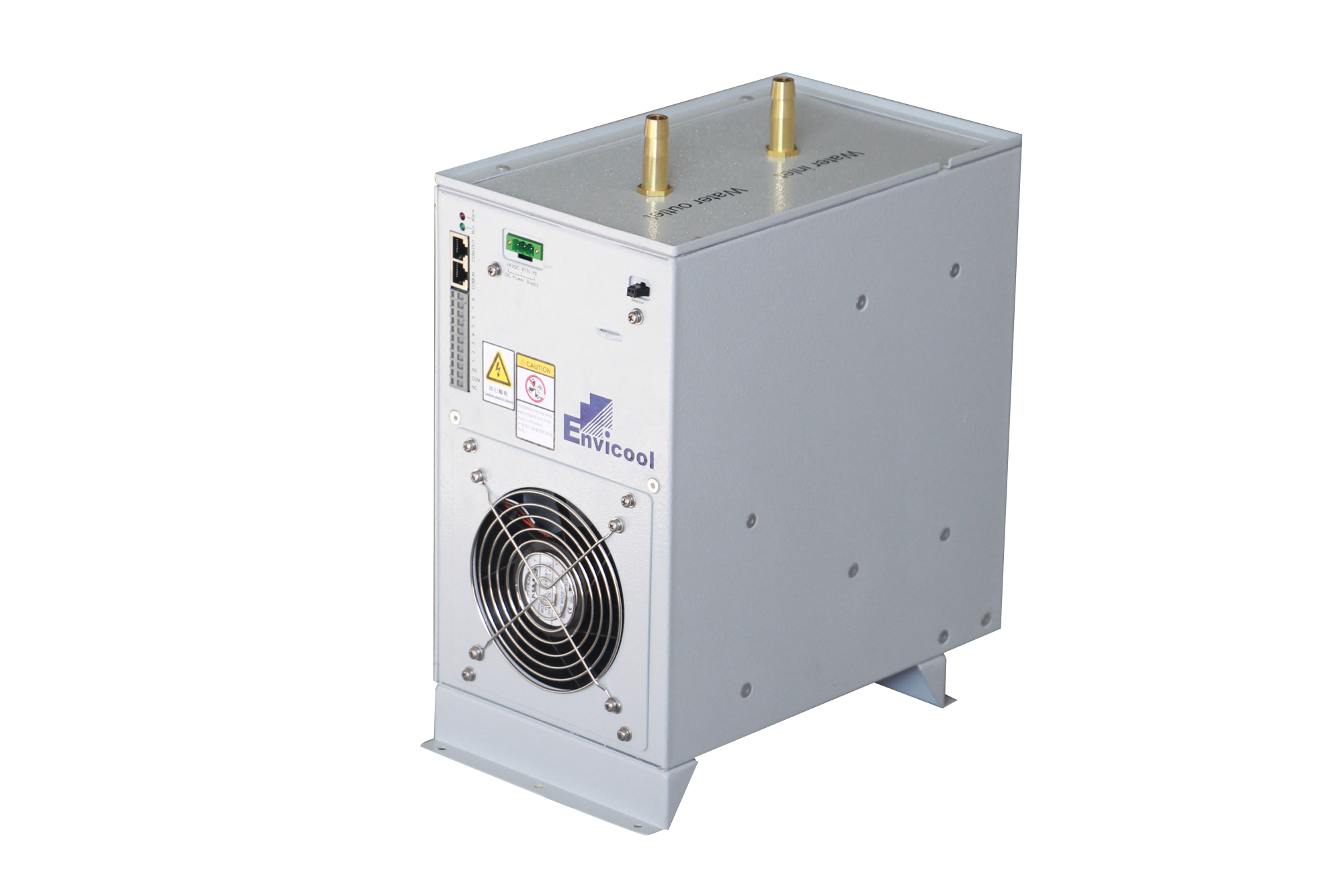
Select the micro water chiller around the instrument’s thermal requirement
Envicool's EIW micro chiller is described for indirect liquid cooling inside in-vitro testing instruments. Its official page states a 2–4°C water-temperature range and identifies a DC variable-frequency compressor refrigeration system, intelligent controller and water system. The original equipment image shows a compact enclosure with two top fluid connections, a fan and electrical/control interfaces. It does not provide a medical-device approval, selected cooling capacity or a complete instrument integration drawing.
The useful selection problem is maintaining the instrument's required cooling-water conditions at its actual heat load without equating chilled water with validated reagent or assay performance. High precision, quiet operation and service life above ten years are supplier statements without inspected accuracy, sound or lifecycle test reports. This brief requires an instrument-specific thermal/hydraulic selection and control acceptance; it does not infer coolant chemistry, pump head or the numerical capacity from a broader cabinet-cooling reference elsewhere on the page.
Published parameters and their scope
This is an equipment family; its range does not identify one orderable configuration.
- Family designation
- EIW micro-chiller family
Swipe the table, or focus it and use arrow keys, to read the conditions and sources.
| Parameter | Published value | Conditions and evidence |
|---|---|---|
| Published application | Indirect liquid cooling for in-vitro testing instruments | Supplier equipment scope; no instrument/regulatory approval inspected. Source |
| Water-temperature statement | 2–4°C | No selected load/ambient/flow conditions or accuracy tolerance supplied. Source |
| Described subsystems | DC inverter compressor, intelligent controls and water system | Exact pump/refrigerant/electrical schedule not issued. Source |
| Monitoring interface | RS485 with alarms/protection | No protocol/register map or selected alarm thresholds reviewed. Source |
| Heat-exchanger/service feature | Wide fins and adjustable fan speed | No dust-loading or sound test data inspected. Source |
| Missing rating evidence | Capacity, pump curve, stability, sound and fluid limits | No capacity inferred from broader 300–4000 W solution text. Source |
| Supplier lifecycle claim | Service life >10 years | Not an independently reviewed life test or warranty term. Source |
Selection and application review
Define the instrument water duty at its real load
Obtain the instrument OEM's allowed supply/return temperatures, flow, pressure, heat load and permitted transients. Ask for selected EIW capacity and complete input at these conditions and the expected installation ambient. The 2–4°C statement does not prove that any unidentified model holds that water range at every heat load.
Specify whether temperature stability and recovery time are critical to the instrument. Obtain numerical tolerances and test conditions from the selected equipment schedule; high-precision marketing provides no stated accuracy. Do not substitute water temperature for measured reagent temperature.
Close the fluid circuit and condensation boundary
Request pump performance, permitted fluid chemistry, wetted materials and connection dimensions. Define the circuit's resistance, reservoir/fill scope, venting and maintenance requirements. A compact image with two fittings does not issue flow, pressure or seal compatibility.
Agree insulation and condensation management with the instrument designer at the required water temperatures and environmental humidity. Obtain the manufacturer's operating limits and control method. No universal condensation-free statement or instrument enclosure rating is inferred.
Integrate power, alarms and restart with the instrument
Request supply voltage/current, protective requirements, RS485 protocol and register map for the actual model. Agree sensor locations, high/low-temperature and flow alarms, and how the instrument responds when cooling is unavailable. The source names communications without defining the protocol.
Check power-on/startup and recovery behaviour against the instrument's permitted sequence. The page's DC compressor wording does not establish the complete unit supply or a specific low-voltage input. Use an issued wiring and control diagram.
Assess compact installation and heat rejection
Obtain selected dimensions, mass, air direction, ventilation clearances and service access. The refrigeration heat rejected to surrounding air and the installation compartment must be included in the instrument thermal assessment. No footprint or exhaust requirement is invented from the photo.
Request sound data at the selected compressor/fan duty and the actual filter/coil cleaning procedure. Wide-fin and long-maintenance-interval statements have no inspected dust test or fixed service interval here.
Accept chiller performance separately from assay validation
Agree thermal/hydraulic duty, temperature stability and control/fault checks using defined loads, ambient conditions and instruments. Separately validate the complete testing instrument under its OEM procedures; the chiller's water-temperature result does not establish clinical or assay accuracy.
Current price, lead time, independently measured duty and a regulatory approval for an integrated instrument remain unknown.
Issue OEM water limits
Define heat load, temperatures, flow/pressure and transient requirements.
Approve integration
Close fluid materials, insulation, power, communications and heat-rejection access.
Verify separate outcomes
Accept chiller thermal/control duty, then validate the complete instrument independently.
Sources and review scope
Compiled by HVACDeck Editorial. Source review identifies what the publication states; it is not an independent performance test or certification.
- Official EIW micro medical chillerChecked 2026-10-11 · Full water-range/system/interface description and original compact-unit image read; no numerical duty or approval report available.
Editorial method and corrections · Report a detail with this page URL
Turn the evidence into an enquiry
Send the manufacturer your required duty, installation conditions and the unresolved items identified in this brief.
Other equipment from this manufacturer
Envicool MC power-container cooling · Heating, humidity and dry contacts
Envicool BattCool-AC container cooling · Air paths and standby control
Envicool BattCool-C / EMW chillers · Battery coolant and fault duty
Envicool EMA cabinet air conditioners · Air path and filter service
Envicool HC combo cabinet cooling · Heat-pipe and compressor modes
Envicool DC / EC outdoor cabinet cooling · Power and selected duty