
Published operating leads
Single-stage geared construction, guide-vane/diffuser control, backup oil and low-voltage soft-start description.
 HVAC & REFRIGERATION
Evaluate the compressor operating envelope and emergency shutdown together with the complete heat-rejection assembly.
From Xinwuxin · Wuhan process-refrigeration equipment
Individual product research · HVACDeck Editorial · Sources checked 2026-10-11
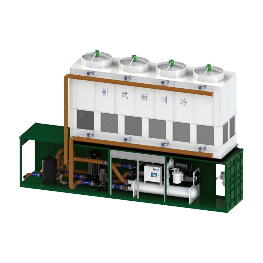
Xinwuxin’s integrated centrifugal chiller uses a supplier-described single-stage geared centrifugal compressor with a semi-hermetic motor. Its official body identifies inlet guide vanes, a movable diffuser arrangement, an emergency oil supply and an onboard soft-start cabinet for the low-voltage series. The original illustration places the compressor/vessel package beneath an upper heat-rejection enclosure with connecting pipes. This is a supplier assembly illustration, not a verified shipped unit or an issued refrigeration P&ID.
The original YDLSRTBMS table covers several large model sizes and gives cooling, input, flow, mass and overall dimensions. It does not accompany those values with the simultaneous fluid and heat-sink conditions needed to validate a selected rating. This page focuses on the centrifugal machine’s operating envelope, surge control, oil-supported shutdown and assembled installation boundary. It does not create separate pages for each nominal tonnage or turn narrative efficiency/noise claims into independently tested performance.
This is an equipment family; its range does not identify one orderable configuration.
Swipe the table, or focus it and use arrow keys, to read the conditions and sources.
| Parameter | Published value | Conditions and evidence |
|---|---|---|
| Published compressor construction | Single-stage geared centrifugal; semi-hermetic motor | Supplier narrative; actual compressor maker/model and issued mechanical schedule required. Source |
| Capacity-control description | Inlet guide vanes and movable diffuser; supplier states 10–100% regulation | Supplier claimed operating range, not an independently established surge-free map. Source |
| Illustrative model row | YDLSRTBMS500.1: 1758 kW cooling / 301 kW input; COP 5.8 | Original table; simultaneous thermal conditions and input-package boundary absent. Source |
| Illustrative circuit flows | YDLSRTBMS500.1: 302 m³/h chilled / 354 m³/h cooling water | Original labelled table flows; entering/leaving temperatures are not provided for final hydraulic/thermal selection. Source |
| Illustrative equipment/operating mass | YDLSRTBMS500.1: 14800 / 17020 kg | Original table; actual shipping splits, support loads and filled boundary must be issued. Source |
| Emergency oil-supply description | Backup oil cylinder and oil-return arrangement | Supplier describes oil-supported stop during pump fault or power loss; actual test and endurance boundary unverified. Source |
| Low-voltage starting lead | Onboard soft-start cabinet | Supplier series statement; actual voltage, full-load current and protective schedule require confirmation. Source |
For YDLSRTBMS500.1 the original table lists 1758 kW cooling, 301 kW input and COP 5.8, alongside 302 m³/h chilled-water and 354 m³/h cooling-water flow. The page does not specify the corresponding entering/leaving temperatures or heat-rejection condition. These supplier numbers are a conditional enquiry reference, not a commissioned site rating.
Issue the actual load profile, fluid temperatures, flow limits and site heat sink. Request a selected compressor/plant performance map including minimum stable load and the limits at changing heat-rejection conditions. The source’s model sizes and nominal refrigeration tons remain together on this family page; a larger table row does not establish that one quoted package meets every project duty.
The supplier describes a movable diffuser coordinated with inlet-guide-vane opening to regulate discharge passages, and claims continuous operation over 10–100% without surge. No independently reviewed map or test demonstrates that range at every pressure ratio, fluid condition or transient. Ask for the actual compressor’s permitted envelope and the controls used to stay within it.
Agree startup, unloading, minimum-flow/load behaviour and protective responses when heat rejection or process demand changes. Require the supplier to distinguish normal regulating actions from a protective stop. The page does not prescribe a universal surge setpoint or controller tuning; those must be issued for the selected machine by the responsible supplier/OEM.
The body describes a backup oil cylinder for every centrifugal compressor and an oil-return method intended to support a stop when the oil pump fails or power is lost. Treat that as a specific protective-system claim to verify, rather than a promise that all unforeseen events can occur safely without further design.
Request the oil circuit, lubrication monitoring, backup-supply boundary, shutdown sequence and test evidence for the actual compressor. Agree how pump fault, supply loss and restart permission are handled. The website’s ‘theoretical unlimited’ bearing-life wording is not a service-life guarantee and is not used to assign replacement or inspection intervals. Obtain the actual written maintenance and overhaul schedule.
The description says the low-voltage series includes an onboard soft starter with motor cable connection, phase sequence and overcurrent/temperature/voltage protection. It does not identify one universal supply voltage, starting current or cabinet ingress rating for all YDLSRTBMS rows. Have the quotation issue the exact supply, complete load list, starting behaviour and site electrical interfaces.
The supplier attributes 4–7 dB(A) reduction to refrigerant injection at the compressor discharge and quotes motor efficiency up to 96%. No reviewed comparator, acoustic method or selected motor test establishes those as complete-package results. Require the actual sound-report and electrical-input boundary when those affect the purchase; do not compare isolated component figures with a competitor’s entire plant.
The source table gives an overall shared 12000 × 2400 × 7560 mm size cell, while the separate labelled drawing breaks the assembly into several dimensions. Some mass rows change unexpectedly between adjacent larger model codes. No attempt is made to repair those figures by intuition. The supplier itself asks for civil drawings before construction and a project-specific design confirmation.
Obtain a corrected general arrangement, transport/module splits, lifting plan, dry/filled masses, foundation reactions and service-removal access. Close the heat-rejection enclosure, pumps, water treatment, connecting piping and control/commissioning responsibility. The illustration does not establish that every component is included or that one transport container contains the assembled system.
Single-stage geared construction, guide-vane/diffuser control, backup oil and low-voltage soft-start description.
Simultaneous rating point, surge/low-load map, corrected electrical and mass data, issued P&ID and GA.
Thermal duty, total included input, regulating/protective behaviour and oil-supported shutdown tests at the ordered conditions.
Compare quotations against the same cooling/heat-rejection conditions, minimum-load requirement, complete electrical boundary and installed scope. Ask which compressor and pressure-equipment manufacturers supply the order and which current documents accompany each assembly. Enterprise recognition and a general business licence do not certify centrifugal performance or pressure-equipment manufacture.
Current price, lead time, independently measured efficiency and purchaser-side acceptance results were not established. The platform wrote this dossier from the actual centrifugal description and original schedules; it has not operated the machine. The result is an enquiry that tests the distinctive operating and installation responsibilities of this construction rather than a generic industrial-chiller description.
Request a selected performance/operating map including the minimum-load and transient envelope.
Identify compressor, lubrication protections, starter, pressure boundaries and integrated assemblies.
Use corrected GA/load data and agreed thermal, regulating and emergency-stop verification.
Compiled by HVACDeck Editorial. Source review identifies what the publication states; it is not an independent performance test or certification.
Editorial method and corrections · Report a detail with this page URL
Send the manufacturer your required duty, installation conditions and the unresolved items identified in this brief.
Xinwuxin air-cooled screw chillers · Ambient and circuit selection
Xinwuxin parallel screw packages · Compressor and oil-system scope
Xinwuxin container ice systems · Production, storage and conveying
Xinwuxin XIL flake-ice machines · Output, power and discharge
Xinwuxin integrated chillers · Package and site interfaces
Xinwuxin screw chillers · Water and secondary-fluid selection