
Water-cooled condenser assembly
Published illustration includes a tower, water piping and pumps beside the liquid chiller; request both circuit schedules.
 HVAC & REFRIGERATION
Compare the two heat-rejection assemblies and agree what is factory supplied before committing to foundations and site piping.
From Xinwuxin · Wuhan process-refrigeration equipment
Individual product research · HVACDeck Editorial · Sources checked 2026-10-11
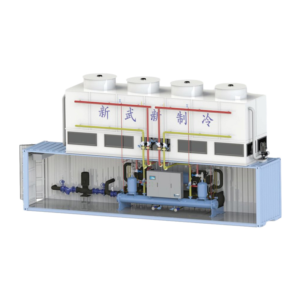
Xinwuxin’s integrated screw-chiller system brings refrigeration and heat rejection into an assembled package. Its official page explicitly illustrates a water-cooled condenser arrangement and an evaporative-condenser arrangement. In the first illustration, a cooling-tower assembly, connecting water piping and pumps accompany the chiller on a base. The second shows refrigeration assemblies beside an evaporative heat-rejection enclosure. These are supplier layout illustrations; they are not piping-and-instrumentation diagrams or photographs of a witnessed installation.
This package is relevant when a buyer needs to close the interfaces among the chiller, condenser circuit, pumps, controls and civil works. An original model table gives capacities, masses and large assembly dimensions, but does not state the simultaneous fluid and heat-sink rating conditions needed to validate its COP. The page also repeats a valve paragraph under PLC and places fan-control wording under an evaporator heading. This assessment uses the actual assembly evidence and flags those gaps instead of treating the repeated marketing text as a complete engineered bill of materials.
This is an equipment family; its range does not identify one orderable configuration.
Swipe the table, or focus it and use arrow keys, to read the conditions and sources.
| Parameter | Published value | Conditions and evidence |
|---|---|---|
| Two documented heat-rejection layouts | Water-cooled condenser / evaporative condenser | Original supplier-labelled assembly illustrations; not an issued P&ID. Source |
| Published model example | YDLSLGBMZ210.1: 224.1 kW cooling; 41.2 kW input | Original table values only. Simultaneous thermal rating conditions are absent from the reviewed page. Source |
| Example transport and operating mass | YDLSLGBMZ210.1: 7500 / 8625 kg | Supplier table; dry/operating mass labels read. Final ordered shipping/lifting data required. Source |
| Example assembly size | Single-head group: 12000 × 2400 × 3400 mm | Shared table cell, not verified container standard, transport envelope or final ordered GA. Source |
| Published site access note | More than 1 m operation/maintenance space around equipment | Supplier guidance, not a complete airflow, lifting or statutory clearance design. Source |
| DCS connection lead | Modbus RTU through RS485 | Supplier description; I/O list, register map and permitted command boundary not supplied. Source |
The water-cooled illustration shows a tower linked to the chiller and pumps by external pipes. The second is expressly labelled an evaporative-condenser system. These indicate different heat-rejection boundaries even when both are offered as integrated equipment. An illustration cannot establish every valve, sensor, bypass, drain or safety component included in a quotation.
Obtain the issued P&ID and equipment schedule for the selected alternative. Identify the load-water circuit, condenser or spray-water circuit, makeup/drain connections and water-treatment responsibility. The page cites a cooling-water design standard by number, but the current edition and project compliance were not verified here. Require a water-quality specification and a responsible project review rather than assuming tower water and process fluid may share one loop.
Published illustration includes a tower, water piping and pumps beside the liquid chiller; request both circuit schedules.
Published illustration places the heat-rejection enclosure beside refrigeration assemblies; require the actual refrigerant/spray-water boundary.
Purchased components, treatment, valves, field piping, electrical feeds and commissioning responsibilities.
For YDLSLGBMZ210.1 the original table lists 224.1 kW cooling, 41.2 kW input, COP 5.4, 39 m³/h chilled-water flow and 478 kW in a column labelled evaporative-condenser heat rejection. No matching entering/leaving-fluid or ambient/condensing point accompanies that table. The quoted COP therefore cannot be a site selection or a comparison with the separate screw-chiller schedule.
Some electrical cells repeat input-power numbers in a current column, and several dual-head entries make the input-power boundary unclear. Ask whether electrical figures cover one compressor, all compressors or the whole package, including pumps and fans. A written corrected selection sheet must reconcile cooling duty, total input, heat rejection and flow at one simultaneous condition. This page does not silently double values or recalculate a replacement supplier rating.
The table gives 7500 kg equipment mass and 8625 kg operating mass for YDLSLGBMZ210.1 and a shared 12000 × 2400 × 3400 mm dimension cell across single-head entries. Those are catalogue assembly figures, not an approved lifting instruction, shipping-container certificate or point-load schedule. The separate original illustration shows a container-like lower housing, but its presence alone does not establish freight certification.
Have the supplier issue module splits, transport dimensions, lifting points, centre of gravity, support reactions and final filled mass. The page instructs customers to submit civil drawings before construction and allow more than 1 m around the equipment. Confirm additional tower airflow, maintenance removal and rigging space against the selected arrangement; a general 1 m note cannot settle every access requirement.
The body describes outlet-water PID regulation, operating records, alarms, password levels and a Modbus RTU interface through RS485. It also describes fan-count control for the evaporative unit, although that paragraph sits under an evaporator heading. This editorial assessment treats it as a supplier control description and does not infer a verified counterflow evaporator construction from the misplaced title.
Request the actual controller and motor-starting schedule, pump/fan sequences, freeze/flow protections and restart behaviour. Agree which package states go to the customer DCS, which commands may return and how locally required protections behave if communications fail. The repeated electronic-valve wording under PLC does not establish a specific PLC brand or a complete control architecture.
An integrated proposal can shift design, piping and assembly work to the supplier, but the website’s claimed floor-area and installation-time savings lack a reviewed baseline. Require a comparison of the actual alternative scopes and programme assumptions instead of budgeting a universal percentage saving.
Request a corrected thermal/electrical selection, issued P&ID and general arrangement, factory inspection records and site commissioning plan. Agree who provides utilities, water treatment, foundation works, external pipework and operator training. Current price, delivery and independently witnessed performance are unknown; the useful outcome of this brief is a package boundary that makes two quotations technically comparable.
Provide site climate, water availability and the process-fluid duty for the proposed circuit.
Close pumps, treatment, electrical feeds, controls, piping and factory-versus-field scope.
Use corrected ratings, issued drawings, support loads and a documented commissioning/test schedule.
Compiled by HVACDeck Editorial. Source review identifies what the publication states; it is not an independent performance test or certification.
Editorial method and corrections · Report a detail with this page URL
Send the manufacturer your required duty, installation conditions and the unresolved items identified in this brief.
Xinwuxin integrated centrifugal chillers · Surge, oil and site scope
Xinwuxin air-cooled screw chillers · Ambient and circuit selection
Xinwuxin parallel screw packages · Compressor and oil-system scope
Xinwuxin container ice systems · Production, storage and conveying
Xinwuxin XIL flake-ice machines · Output, power and discharge
Xinwuxin screw chillers · Water and secondary-fluid selection