
Evaporative condensing
Published low-temperature conditions use a 35°C condensing temperature; site weather and condenser selection must be issued.
 HVAC & REFRIGERATION
Choose the fluid, condenser circuit and compressor-head arrangement together, then resolve the published rating conflicts.
From Xinwuxin · Wuhan process-refrigeration equipment
Individual product research · HVACDeck Editorial · Sources checked 2026-10-11
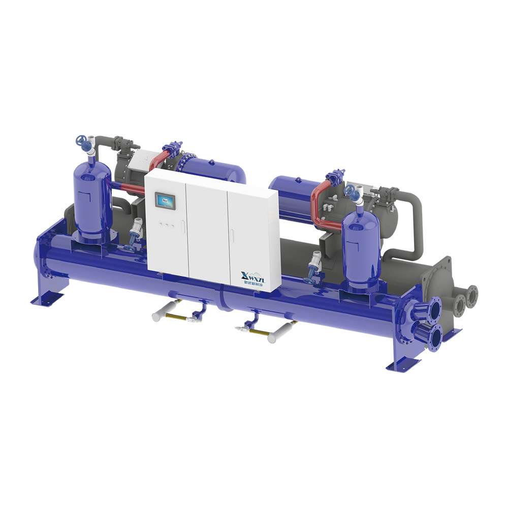
Xinwuxin’s screw-chiller offer uses twin-screw compression and distinguishes evaporative-condensing and water-cooled heat rejection. Its official page separately schedules water and low-temperature secondary-fluid duties and single/twin compressor-head constructions. The original illustration shows a blue assembled liquid-cooling skid with compressors, vessels, flanged pipe connections and a control enclosure. It is a supplier illustration, not an independently inspected delivered unit.
This brief consolidates the model sizes and −5, −10 and −15°C outlet cases into one genuine family rather than creating temperature or capacity pages. Selection depends on the fluid and heat sink together. The source contains reversed-looking water temperatures, copied condenser notes, questionable power/COP relationships and inconsistent dimension tables. Illustrative model values are therefore bounded to the exact published row and condition; obtain corrected current data before sizing utilities or placing an order.
This is an equipment family; its range does not identify one orderable configuration.
Swipe the table, or focus it and use arrow keys, to read the conditions and sources.
| Parameter | Published value | Conditions and evidence |
|---|---|---|
| Compression and capacity control | Twin screw; staged 25 / 50 / 75 / 100% or continuous regulation | Supplier alternatives, not confirmation that both schemes are fitted to every selected unit. Source |
| Published exchanger construction | Flooded evaporator; enhanced copper heat-transfer tubes | Supplier description; issued tube/material and pressure schedules still needed. Source |
| Low-temperature fluid mapping | YC: ethylene-glycol solution; YS: calcium-chloride solution | Exact supplier footnote; concentration and material compatibility are not stated. Source |
| Evaporative example at −10°C outlet | JYC/YSLGBGE190.1: 105 kW cooling / 34 kW input; COP 3.06 | Published low-temperature row at −5/−10°C fluid, 35°C condensing, 380 V three-phase 50 Hz; supplier data, not a measured guarantee. Source |
| Water-cooled example | LSLGBMS120.1: 112 kW cooling / 25 kW input; COP 4.44 | Single-head table; footnotes 7/5°C water and 32/37°C condenser water. Column consistency requires supplier confirmation. Source |
| Control integration | Modbus RTU through RS485 to the customer DCS | Published protocol/interface only; register map, bus settings and remote-control permissions missing. Source |
| Unresolved rating boundary | 5/7°C vs 7/5°C; mixed condenser footnotes and questionable table cells | No silent corrections or extrapolation to a full-family guaranteed range. Source |
The official low-temperature schedules give 0/−5, −5/−10 and −10/−15°C inlet/outlet pairs. Their footnotes identify YC as ethylene glycol and YS as calcium chloride. They are secondary fluids circulating through the load side, not refrigerant names. The same nominal model number at different fluid temperatures does not retain the same published cooling capacity.
Issue the exact fluid, concentration, temperature limits and system material restrictions to the supplier. Obtain selected flow, pressure drop, freeze protection and pump requirements at that composition. No glycol concentration or safe freeze margin was verified, and this brief does not invent either. The refrigerant examples in the electronic-expansion-valve paragraph contain malformed identifiers, so they are not used as an ordered-unit refrigerant schedule.
For the evaporative low-temperature example JYC/YSLGBGE190.1 at −10°C outlet, the source’s visually reviewed row gives 105 kW cooling, 34 kW input and COP 3.06. Its surrounding conditions are −5/−10°C secondary fluid, 35°C condensing temperature, the supplier’s stated fouling factor 0.044 m²·°C/kW and 380 V three-phase 50 Hz. The condenser temperature is not an ambient dry-bulb or wet-bulb design condition.
The single-head water-cooled LSLGBMS120.1 row gives 112 kW cooling, 25 kW input and COP 4.44. Its text states 7/5°C load water and 32/37°C condenser water. These source examples describe different circuits and cannot establish which consumes less electricity at an actual site. Ask for both selections at the same load, weather/utility conditions and electrical package boundary.
The evaporative water notes print inlet/outlet as 5/7°C. The dual-head water-cooled heading repeats an evaporative 35°C condenser note. Some dual-head water-cooled power and COP columns appear inconsistent with their cooling capacity, and the final low-temperature table repeats COP 2 across unlike rows. These conflicts are not normalised into clean-looking guaranteed specifications.
Dimension drawings add another reason to request an issued general arrangement: one dual-head water-cooled group prints overall length C as 1650 mm, conflicting with adjacent rows and the earlier table. Other drawing dimensions conflict with the performance-table sizes. Do not use those cells to order foundations or set lifting plans. The supplier itself says actual and nonstandard units may differ from the catalogue.
The description allows staged or continuous loading and attributes oil feed to pressure difference, with oil separation and a flooded evaporator. Ask for the actual compressor supplier/model, selected loading scheme, minimum operating duty and the written restart/low-load limits. A twin-head drawing indicates two assemblies; it does not establish automatic redundancy or full capacity with one head unavailable.
The controls paragraph gives a touchscreen, PID outlet-water regulation, operating records, alarms and Modbus RTU/RS485. Request a controls narrative and register list tied to the supplied controller. Agree what the customer DCS may read or command and how local protections remain authoritative. A communication interface is not evidence of compatibility with every DCS or of unattended fault recovery.
Identify whether a quotation includes only the refrigeration skid or the condenser, pumps, treatment, valves, starter and site piping. The screw page and the separate integrated system do not have identical assembly boundaries. Compare total electrical input, hydraulic requirements, heat-rejection duty and physical service access using the same delivered scope.
Require a dated corrected rating sheet, pressure/material documentation, approved drawings and agreed thermal/control acceptance tests. Actual price, delivery, witnessed efficiency and independent installed results remain unknown. Treat the source values as an enquiry starting point, with the listed conflicts requiring a written supplier response.
Published low-temperature conditions use a 35°C condensing temperature; site weather and condenser selection must be issued.
Selected condenser-water flow/temperatures and water treatment must be included in the comparison.
Compare the extra heat-rejection and piping package boundary rather than the screw compressor alone.
Compiled by HVACDeck Editorial. Source review identifies what the publication states; it is not an independent performance test or certification.
Editorial method and corrections · Report a detail with this page URL
Send the manufacturer your required duty, installation conditions and the unresolved items identified in this brief.
Xinwuxin integrated centrifugal chillers · Surge, oil and site scope
Xinwuxin air-cooled screw chillers · Ambient and circuit selection
Xinwuxin parallel screw packages · Compressor and oil-system scope
Xinwuxin container ice systems · Production, storage and conveying
Xinwuxin XIL flake-ice machines · Output, power and discharge