
Envicool rack loadbanks · Liquid-cooling test scope
Specify load steps, electrical/fluid interfaces and protective unloading before using the rack to witness a cooling duty.
From Shenzhen Envicool Technology Co., Ltd.
Individual product research · HVACDeck Editorial · Sources checked 2026-10-11

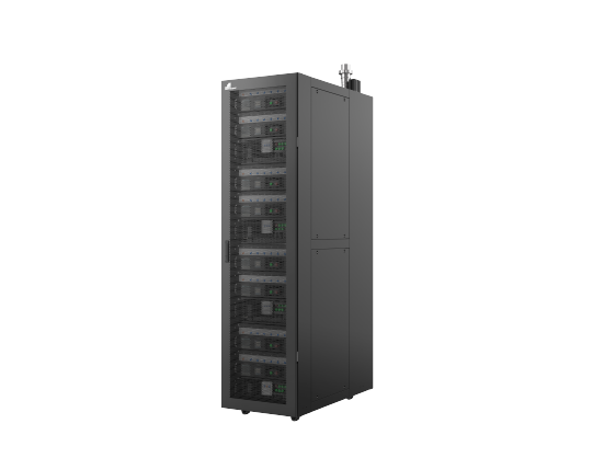
Define the test heat load and protection boundary before commissioning
Envicool's rack-level loadbank is a resistive liquid-cooling test assembly. The official description says load is added or removed by switching miniature circuit breakers, with rear electrical aviation-plug inputs and rear sanitary-flange fluid connections. It describes emergency stop, branch short-circuit protection, staged temperature-triggered unloading, grounding and a manually adjustable ball valve for flow-resistance simulation. The original image shows stacked modules in a rack cabinet, without an issued electrical or hydraulic schedule.
This equipment produces a test heat load; it is not a chiller and is not evidence that the connected cooling installation already performs as required. ORV3 compatibility and GB 200 heat-simulation wording are supplier features whose exact mechanical/load profile must be confirmed. No total kW, voltage, current, load-step accuracy or sensor calibration was published in the reviewed text. This brief helps define a controlled test and acceptance file without assigning a capacity from the visible module count.
Published parameters and their scope
This is an equipment family; its range does not identify one orderable configuration.
- Family designation
- Rack-level liquid-cooled loadbank
Swipe the table, or focus it and use arrow keys, to read the conditions and sources.
| Parameter | Published value | Conditions and evidence |
|---|---|---|
| Test mechanism | Liquid-cooled resistive power-consumption modules | Produces heat for testing; not cooling equipment. Source |
| Load switching | MCB on/off adds or subtracts load | No published selected step size or total electrical schedule. Source |
| Connections | Rear aviation-plug electrical input; sanitary-flange fluid inlet/outlet | Exact ratings, pinout and flange dimensions not reviewed. Source |
| Protection features | Emergency stop, branch short circuit, thermal unloading and grounding | Actual thresholds, circuits and acceptance checks needed. Source |
| Hydraulic simulation | Manual ball valve adjusts node flow resistance | Not an automatically calibrated server pressure-drop model. Source |
| Supplier compatibility wording | ORV3 rack; GB 200 heat simulation | No inspected certified-fit or actual workload validation report. Source |
| Rating gaps | Total kW, voltage/current, sensor accuracy and unloading times | No values inferred from module rendering. Source |
Selection and application review
Translate the cooling test into an issued load schedule
Define required heat load, load steps/ramp, duration and relevant failure cases. Obtain the selected total/branch kW, voltage, current and electrical supply arrangement. The visible stack of modules does not establish a capacity or number of equal-rated branches.
If GB 200 simulation is required, specify which thermal/hydraulic and mechanical characteristics must be represented. A resistive test load can assess defined cooling conditions without being a complete emulator of a real server workload. Confirm the intended equivalence and its limits.
Close electrical and hydraulic interfaces
Request plug pinout/ratings, cable sizing, protective devices, grounding instructions and the selected electrical schematic. Separately specify coolant composition, temperatures, flow, pressure and flange dimensions. A named connector style is not enough to approve either connection.
Obtain the hydraulic resistance curve and permitted flow for the selected load modules. Agree the ball-valve setting and measurement method used to simulate rack-node resistance. A manual valve position alone is not a traceable match to a server pressure-drop curve.
Agree protective unloading and operator response
Ask for emergency-stop locking behaviour, branch short-circuit protection and overtemperature thresholds for module, resistor and control chambers. Obtain the configured staged-unloading time and the documented response during inadequate flow or loss of coolant supply.
Agree tests for alarms, safe loading inhibition and restart. The website's protection descriptions are not an inspected circuit validation or operating procedure. Use the issued instructions and a defined test authority for energising and servicing the loadbank.
Make measurement accuracy part of the test file
List required flow, temperature, pressure and electrical measurements and their calibration/uncertainty. The accurate-sensors feature does not publish an accuracy class or make displayed values independently certified. Establish data logging and measurement boundaries before witnessing cooling performance.
Separate electrical input to the resistive loads from auxiliary power and heat losses relevant to the chosen thermal balance. Specify where inlet/outlet temperatures and flows are measured. No inferred total heat duty is calculated from an unspecified instrument reading.
Accept the loadbank and cooling system as separate items
Check the ordered loadbank's step control, interfaces, measurement records and protection operation. Then conduct the cooling-system test at agreed conditions using the accepted instrumented load. One successful loadbank function check is not a certificate of plant capacity.
Current price, lead time, certified platform fit and independently validated load accuracy remain unknown.
Issue test conditions
Define total/step load, fluid duty, duration and required simulation boundary.
Approve interfaces/protection
Check electrical/fluid schematics and actual unloading/alarms.
Witness with calibrated data
Accept the loadbank first, then report cooling performance at agreed measured conditions.
Sources and review scope
Compiled by HVACDeck Editorial. Source review identifies what the publication states; it is not an independent performance test or certification.
- Official rack-level loadbank pageChecked 2026-10-11 · Full mechanism and protection text plus original modular-rack rendering read; no numerical selected ratings published.
Editorial method and corrections · Report a detail with this page URL
Turn the evidence into an enquiry
Send the manufacturer your required duty, installation conditions and the unresolved items identified in this brief.
Other equipment from this manufacturer
Envicool MC power-container cooling · Heating, humidity and dry contacts
Envicool BattCool-AC container cooling · Air paths and standby control
Envicool BattCool-C / EMW chillers · Battery coolant and fault duty
Envicool EMA cabinet air conditioners · Air path and filter service
Envicool HC combo cabinet cooling · Heat-pipe and compressor modes
Envicool DC / EC outdoor cabinet cooling · Power and selected duty