
19/35 °C water
Single module: 66.1 kW at 38 °C return air, 35% RH; published 3.7 m³/h and 33.5 kPa.
 HVAC & REFRIGERATION
Modular indoor air handling with distinctly rated water and return-air conditions; the 67 kW headline is not a universal module duty.
From AIRSYS precision and process cooling
Individual product research · HVACDeck Editorial · Sources checked 2026-10-11
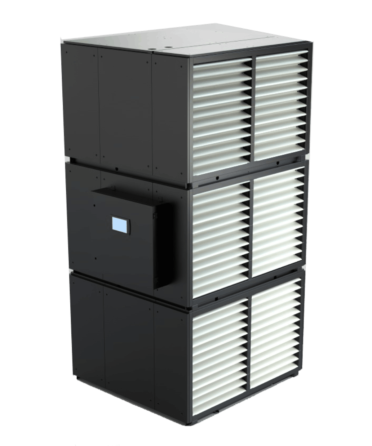
The AIRSYS MAXAIR page links an eight-page English brochure headed MaxAir3. It describes a chilled-water indoor air-handling unit in the PowerOne data-centre system: hot return air passes across a water coil and cooled air is supplied back to the hall. The indoor unit is only one part of that system; chillers, dry coolers, water piping and supervisory operation are separate interfaces.
The webpage rounds its basic module to 67 kW. The brochure's table instead gives 66.1 kW total and sensible capacity at 38 °C return-air dry bulb, 35% RH and 19/35 °C entering/leaving water. It also gives other capacities under other conditions. A buyer should choose the water/air operating envelope first, then obtain a selected module combination and hydraulic design; choosing the largest printed capacity would hide the change in rating conditions.
This is an equipment family; its range does not identify one orderable configuration.
Swipe the table, or focus it and use arrow keys, to read the conditions and sources.
| Parameter | Published value | Conditions and evidence |
|---|---|---|
| One module at condition 1 | 66.1 kW total and sensible; return air 38 °C / 35% RH; water 19/35 °C | Brochure page 7, condition (1); no independent test or site selection. Source |
| Condition 1 hydraulic point | 3.7 m³/h water flow; 33.5 kPa coil water pressure drop | Single-module table at condition (1); piping, header and valve losses are separate. Source |
| One-module air/electrical schedule | 15,500 m³/h; one caseless backward EC centrifugal fan; 3.3 kW maximum unit operating input | Published table. Selected external resistance and installed airflow have not been established. Source |
| Published single-module envelope | 1,620 × 1,200 × 1,130 mm; 260 kg; 400 V / 3-phase / 50 Hz | Brochure dimensions and mass; installation clearance and structural design remain additional requirements. Source |
| Module combinations | 1, 4, 6 or 9 modules shown | Table arrangements with differing dimensions. Multiple-unit header is stated to be supplied by the installer. Source |
For a single module, the brochure prints 66.1 kW at return air 38 °C/35% RH and water 19/35 °C; 83.4 kW at 37 °C/25% RH and water 16/30 °C; and 86.0 kW at 35 °C/30% RH and water 16/24 °C. These are different thermal states, not three speed settings or a guaranteed adjustable capacity range. Request a selection covering the actual load, water temperatures, air condition and operating modes.
A 19/35 °C water design does not mean that every room or IT inlet may operate at those temperatures. The table's return-air condition and the IT equipment's inlet limits belong to different locations. Containment, air mixing and the selected approach temperature need to be demonstrated in the air-distribution design.
Single module: 66.1 kW at 38 °C return air, 35% RH; published 3.7 m³/h and 33.5 kPa.
Single module: 83.4 kW at 37 °C return air, 25% RH; published 4.8 m³/h and 89.6 kPa.
Single module: 86.0 kW at 35 °C return air, 30% RH; the multi-module flow row requires clarification before use.
At condition (3), the table prints 9.3 m³/h in every column from a single module to nine modules, even though the printed cooling capacities increase with module count. This review preserves that discrepancy rather than multiplying and silently replacing the official value. Ask for the corrected hydraulic schedule and the calculation basis.
The brochure explicitly says the multiple-module header is provided by the installer. Obtain branch/whole-assembly flows, valve and strainer scope, connection sizes, balancing strategy, pressure-drop breakdown and the operating sequence. Pump selection cannot use the coil's pressure drop alone; header, pipe and control-valve losses need the project hydraulic design.
The table shows four-, six- and nine-module assemblies as well as one module. The six-module column gives alternative width/height entries of 4,860/3,240 mm and 2,180/3,230 mm, which match the brochure's horizontal or vertical layout concept. Do not assume the alternative numbers describe one simultaneous envelope. Require the selected arrangement drawing, structural support and delivery sequence.
The supplier advertises maintenance from front or back. Confirm which tasks use which side, fan/coil removal paths, lifting requirements and access around headers. A compact 1,620 mm linear footprint claim does not establish the service aisle or structural floor loading for a selected stack.
MaxAir3 is presented with hot-aisle containment and front supply/back return. The brochure discusses mixed rack densities and CFD, but includes no model of the buyer's hall. Obtain the rack heat map, bypass/leakage assumptions, pressure controls, external resistance and inlet-temperature results for normal and failed-module states. Nominal air volume alone is not proof of acceptable rack inlet conditions.
Capacity growth through more modules is distinct from redundancy. Establish the available capacity with one fan, module or water branch out of service and the common dependencies in power, controls and water plant. Include the recovery sequence after power interruption and the alarm/operating points supplied to the site's monitoring system.
The PowerOne brochure discusses PUE below 1.2, climate-dependent free cooling and a Porto Alegre example. The web page uses pPUE wording; those labels must be reconciled before a contract or comparison. The example and advertised savings are supplier scenarios, not measured outcomes for this unit at the buyer's site.
Require a defined energy boundary, climate/load inputs, ancillary power and treatment of backup conditions. Include chillers or dry coolers, pumps, controls and water use where relevant. NetOne's IoT/AI/ML description does not establish an actual point list, licence or cybersecurity configuration; obtain those deliverables separately. Current availability, site saving, warranty and performance guarantees require a signed selection and agreement.
Compiled by HVACDeck Editorial. Source review identifies what the publication states; it is not an independent performance test or certification.
Editorial method and corrections · Report a detail with this page URL
Send the manufacturer your required duty, installation conditions and the unresolved items identified in this brief.
AIRSYS MOBILECOOL-OUTDOOR wall-mounted telecom cooling
AIRSYS DATACOOL-PACKAGE integrated room cooling
AIRSYS CYBERCOOL-MOD CW chilled-water room terminals
AIRSYS CYBERCOOL-MOD DXA air-cooled room cooling