MANUFACTURER / SOURCE REVIEW

AIRSYS precision and process cooling

A Beijing engineering and manufacturing entity within AIRSYS, with a documented Gu'an production history and distinct ICT, medical and semiconductor cooling ranges.

Beijing, Beijing, China

Prepare a technical enquiry
20 published equipment referencesLatest source review 2026-10-11
01 / COMPANY

What this manufacturer offers

AIRSYS Refrigeration Engineering Technology (Beijing) Co., Ltd., 阿尔西制冷工程技术(北京)有限公司, is the legal entity named on the Chinese AIRSYS contact page and in the preserved CRM export. Its recorded business scope includes industrial water chillers and constant-temperature/humidity equipment. The official group catalogue covers equipment-room air conditioning, data-centre cooling, medical imaging chillers and semiconductor process temperature control. These are different engineering duties, with different supply and acceptance requirements.

The website describes manufacturing centres in China and the United States. A National Intellectual Property Administration article dated 18 November 2016 specifically identifies the Beijing company and its Gu'an, Hebei production base. The reviewed technical brochures separately name Gu'an Airsys Environment Technology Company Ltd. Do not assume that the Beijing contact office, the Gu'an workshop and every overseas group company are one legal supplier. Establish who contracts, manufactures, tests and supports the selected equipment.

CRM / official legal identity
阿尔西制冷工程技术(北京)有限公司Exact company name agrees between the original export and the live official contact page; registration data remain dated source records. Source
Current published contact location
14th floor, Tairan Building, Building 1, 36 Gusheng Road, Shijingshan, BeijingContact office on the inspected website; not represented as a production workshop. Source
Dated production reference
2016 CNIPA article names a Gu'an production base opened in 2008Historical report, not a current factory audit or verified present annual capacity. Source
Different product disciplines
ICT air conditioning, medical chillers, semiconductor temperature control and data-centre cooling systemsOfficial group portfolio; actual manufacturing entity and delivered variant must be identified per quotation. Source
Production entity named in brochures
Gu'an Airsys Environment Technology Company Ltd., 25 Dongfang Street, Gu'an Industrial ParkBrochure contact listing; separate entity from the Beijing company, with current site/order scope to be confirmed. Source
02 / EQUIPMENT

Published equipment and selection evidence

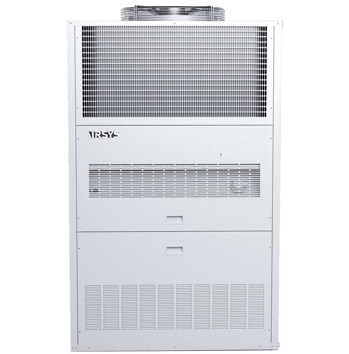
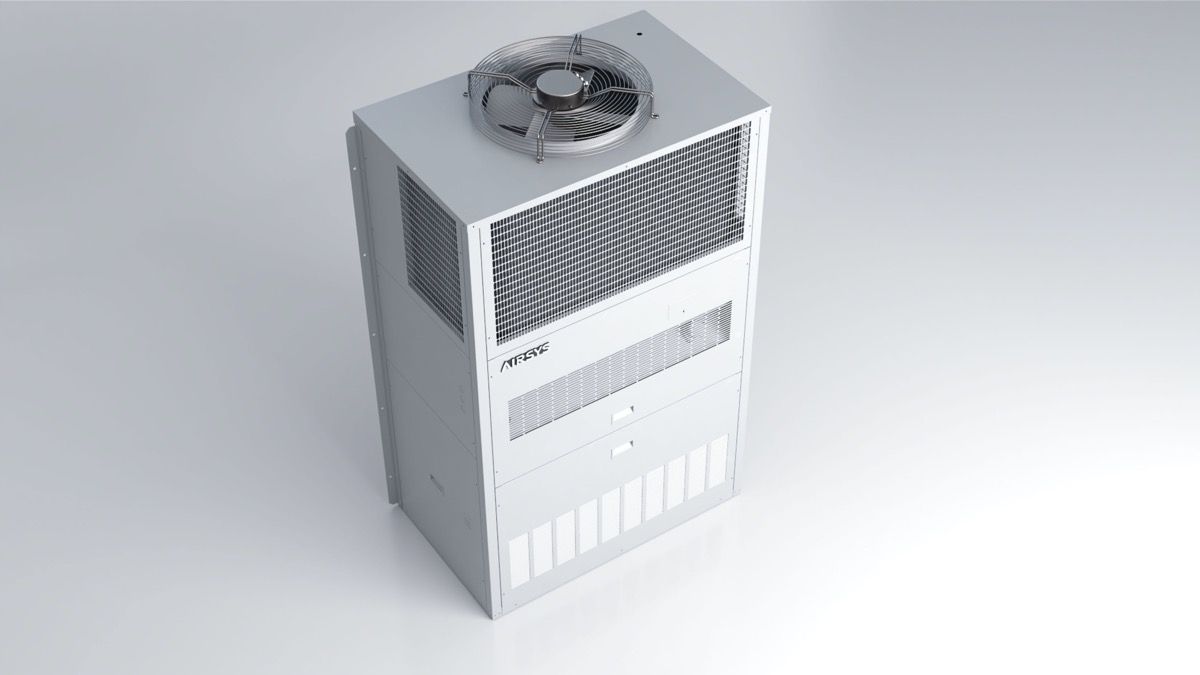
Parameters and source limits · MOBILECOOL-OUTDOOR

Swipe the table, or focus it and use arrow keys, to read conditions and sources.

Manufacturer-published information · MOBILECOOL-OUTDOOR
ParameterPublished valueConditions and evidence
13E1C3 selected table380 V / 3Ph / 50 Hz; 13.2 kW total / 11.1 kW sensiblePDF page 18; outdoor 35 °C and indoor 26.6/19.4 °C. DB/WB notation is not explicitly expanded in this footnote. Source
Electrical duty entries4.3 kW rated / 6.4 kW maximum input; 6.6 A rated; MCA 15 A / MOP 20 ASame model/supply table; installation protection must follow current manufacturer instructions and applicable design. Source
Airflow and refrigerant2,550 m³/h; one EC supply fan; R410A; listed charge 3.7 kg13E1C3 source column. AC or DC fan configuration and charge validity require exact ordered documentation. Source
Direct-air cooling example10.3 kW at Δt 12 °C for 13E1C3Technical footnote calls this an optional function, while webpage calls natural cooling standard; offer must settle the discrepancy. Source
Ambient scopeStandard −30 to +46 °C; extension to +53 °C and −40 °C listed as optionsSource working-range and options pages; useful capacity at limits not supplied. Storage −40 to +70 °C is separate. Source
Parameters and source limits · DATACOOL-PACKAGE

Swipe the table, or focus it and use arrow keys, to read conditions and sources.

Manufacturer-published information · DATACOOL-PACKAGE
ParameterPublished valueConditions and evidence
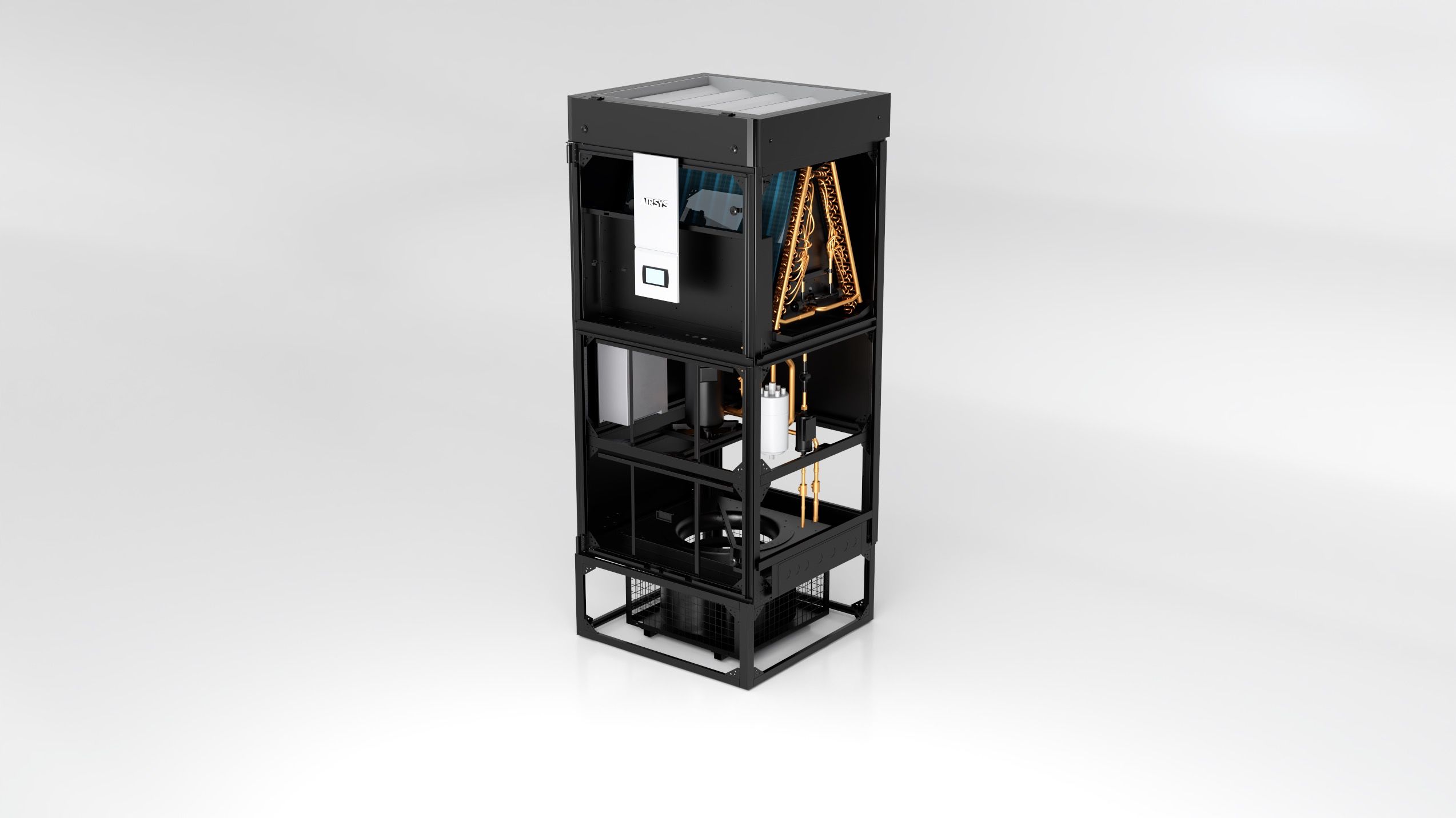
Integrated cooling pathsMechanical refrigeration and direct outside-air coolingOfficial family description; selected duties and ambient/air eligibility limits not supplied. Source
Transport constructionPackaged structure; sectional assembly available for narrow accessSupplier option description, not an issued section size or site joining procedure. Source
Maintenance claimFront access for maintenanceNo current service-envelope drawing or component removal schedule reviewed. Source
Damper descriptionHigh-torque low-leakage damper; opening-to-closing operation stated below 90 secondsSupplier statement, without a leakage test/class or a complete safe-failure sequence. Source
Model ratingsNo selected capacity, airflow, power or dimensions published on the inspected pageUnknown values remain unfilled; another AIRSYS product's table is not substituted. Source
Parameters and source limits · CYBERCOOL-MOD CW

Swipe the table, or focus it and use arrow keys, to read conditions and sources.

Manufacturer-published information · CYBERCOOL-MOD CW
ParameterPublished valueConditions and evidence
100X2 rating set A107.0 kW total / 95.9 kW sensible; return 24 °C, 50% RH; water 7/12 °COriginal PDF page 18 CW table, footnote 2. Source
100X2 hydraulics at set A18.0 m³/h; 55.8 kPa coil plus valve pressure dropSame rating basis. This pressure drop does not include all site piping, strainers and fittings. Source
100X2 rating set B103.1 kW total / 102.1 kW sensible; return 28 °C, 40% RH; water 10/15 °CFootnote 3 changes both air and water; not a water-only comparison. Source
100X2 air movementTwo EC backward-curved fans; 25,000 m³/h; O/U supplyCatalogue table. Downflow fans must descend below the raised floor per its explicit footnote. Source
100X2 power and size380 V / 3Ph / 50 Hz; 22.0 kW maximum operating power; 1,880 W × 990 D × 1,975 H mm; 560 kgIncludes source maximum entry rather than measured fan energy; actual configuration/support need approval. Source
Parameters and source limits · CYBERCOOL-MOD DXA

Swipe the table, or focus it and use arrow keys, to read conditions and sources.

Manufacturer-published information · CYBERCOOL-MOD DXA
ParameterPublished valueConditions and evidence
40E2X1 at 24 °C return43.6 kW total / 41.0 kW sensible; return 50% RH, outdoor 35 °COriginal PDF page 16 DXA table, footnote 2. Source
40E2X1 at 28 °C return46.0 kW total / 44.2 kW sensible; return 50% RH, outdoor 35 °CSame column, footnote 3; different return condition. Source
Compressors / fanTwo fixed-speed scroll compressors; one EC backward-curved fan; 11,500 m³/h40E2X1 source schedule. Circuit independence and failure duty are not established by component count. Source
Electrical maximum380 V / 3Ph / 50 Hz; 18.9 kW maximum operating power, 34.6 A maximum operating currentTable entries, not rated energy use or a provided site protection selection. Source
40E2X1 condenser alternatives2 × CMEG8 at ≤43 °C ambient; 2 × CMEG10 for the ≥43 to ≤52 °C scheduleCatalogue matching footnotes; AMAE/VMEG alternatives are also listed. Exact current selected pairing must be approved. Source
Parameters and source limits · OPTIMA2

Swipe the table, or focus it and use arrow keys, to read conditions and sources.

Manufacturer-published information · OPTIMA2
ParameterPublished valueConditions and evidence
40X0 DXA scheduleR410A; O/U supply; 11,170 m³/h; 460 V / 3Ph / 60 HzCatalogue page 11. This electrical/model schedule must not be transferred to a 50 Hz offer. Source
Variable-speed example40.8 kW total / 40.0 kW sensible at return 29.4 °C DB / 11.1 °C DP, outdoor 35 °CPage 12 first row; another row at the same stated temperatures gives 32.7 / 32.1 kW without naming the speed. No speed assumed. Source
Outdoor condenserVME60 standard; VME80 high-efficiency option40X0 schedule; ordered matching and pipework need approval. Source
Economiser optionsDFC-X0 direct-air arrangement or RPU12 refrigerant pumpBoth optional. RPU12 table lists 0.5 kW and 0.6 m³/h; not the power or air volume of the full cooling system. Source
Electrical maximum26.3 kW maximum operating power; 36.5 A maximum operating current40X0 schedule. These are maximum entries, not the rated compressor input or a supplied site protection design. Source
Parameters and source limits · FREECOOL-HD

Swipe the table, or focus it and use arrow keys, to read conditions and sources.

Manufacturer-published information · FREECOOL-HD
ParameterPublished valueConditions and evidence
Published installationIndoor split construction; UP or DN supplyCatalogue says contact the supplier for outdoor-installed equipment. Indoor ratings do not establish an outdoor offer. Source
48F2 listed airflow / capacity4,750 m³/h; 7.9 / 15.8 / 19 kW at Δt 5 / 10 / 12 °CPDF page 6 technical table; delivered airflow and site thermal suitability still require selection. Source
48F2 electrical entry230 V / 1Ph / 50 Hz; 1.0 kW; 6.1 A; two fansSource table, not a 48 V DC supply despite the nominal model number and another section's DC wording. Source
48F2 unit / shipping size1,150 W × 450 D × 1,320 H mm, 89 kg; packed 1,240 × 540 × 1,480 mm, 99 kgTechnical table explicitly distinguishes equipment dimensions and packaging. Source
Operating / storage range−30 to +55 °C operation; −40 to +70 °C storageCatalogue environment entries, not proof of full useful free-cooling capacity throughout either range. Source
Parameters and source limits · FREECOOL

Swipe the table, or focus it and use arrow keys, to read conditions and sources.

Manufacturer-published information · FREECOOL
ParameterPublished valueConditions and evidence
Cooling methodDirect introduction of cooler outdoor air; coordinated with existing air conditioningOfficial family description; useful operation depends on the room and outside-air conditions. Source
Packaged 18F1 example1,450 m³/h; 2.4 / 4.9 / 5.9 kW at Δt 5 / 10 / 12 °COriginal PDF page 6 performance table; not the split-unit value or a compressor rating. Source
Split 18F1 example1,750 m³/h; 2.9 / 5.9 / 7.1 kW at Δt 5 / 10 / 12 °CSame source table, different construction. Installed flow/external resistance still need selection. Source
Power variantsDC input 36–57 V; AC input 220 V ±15%Catalogue operating range. AC performance table specifically says indoor-installed units; do not infer every layout has either supply. Source
Environment limitsOperation −30 to +55 °C; storage −40 to +70 °CPublished component/working envelope, not an all-weather free-cooling capacity guarantee. Source
Parameters and source limits · CHILLROW

Swipe the table, or focus it and use arrow keys, to read conditions and sources.

Manufacturer-published information · CHILLROW
ParameterPublished valueConditions and evidence
Installed conceptIn-row, rack-adjacent cooling; front horizontal supplyOfficial family arrangement, not a coordinated hall layout or exact connection/dimensional drawing. Source
Cooling formsAir-cooled / chilled-water versionsSeparate forms with different upstream services and test conditions; no selected model reviewed. Source
DXA-specific equipmentVariable-speed compressor, EC fan and electronic expansion valvePage explicitly attaches these components to DXA; not transferred to chilled-water construction. Source
Service constructionHot-swappable fans, pull-out electrical box, two-level condensate traySupplier descriptions; safe procedure, isolation and removal clearance require current instructions. Source
Listed optionsElectric heating/humidification, condensate pump, leak alarm and ATSOptions rather than proof every unit includes these functions. Source
Parameters and source limits · INNOVA Series MDC

Swipe the table, or focus it and use arrow keys, to read conditions and sources.

Manufacturer-published information · INNOVA Series MDC
ParameterPublished valueConditions and evidence
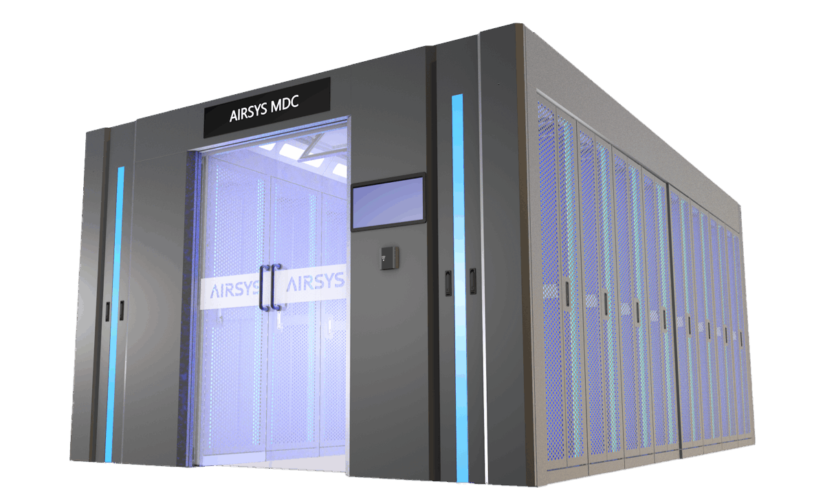
Integrated packageCooling, racks, UPS/distribution, cabling, monitoring and fire-related systemsOfficial INNOVA portfolio; exact included equipment and engineering boundary require the quotation. Source
Double-row / row-cooling exampleUp to 15 kW per IT rack; horizontal supply; air-cooled, water-cooled or chilled-water forms listedCatalogue page 13 configuration, not one universal unit duty or verified installed rack temperature. Source
Double-row / external room-cooling exampleUp to 5 kW per IT rack; downflow coolingCatalogue page 14 arrangement; different air path and power-density scope from page 13. Source
Published illustrative rack2,000 H × 600 W × 1,200 D mm, 42U; 1,500 kg static load; 75% opening ratioDouble-row configuration schedule says dimensions may be customised; platform has not verified structural or thermal acceptance. Source
Monitoring expansionLocal collection and optional 3D/asset/capacity/temperature-map modulesCatalogue pages 37–38 distinguish base local software from expansion software; licence and actual integration not established. Source
Parameters and source limits · ADIACOOL

Swipe the table, or focus it and use arrow keys, to read conditions and sources.

Manufacturer-published information · ADIACOOL
ParameterPublished valueConditions and evidence
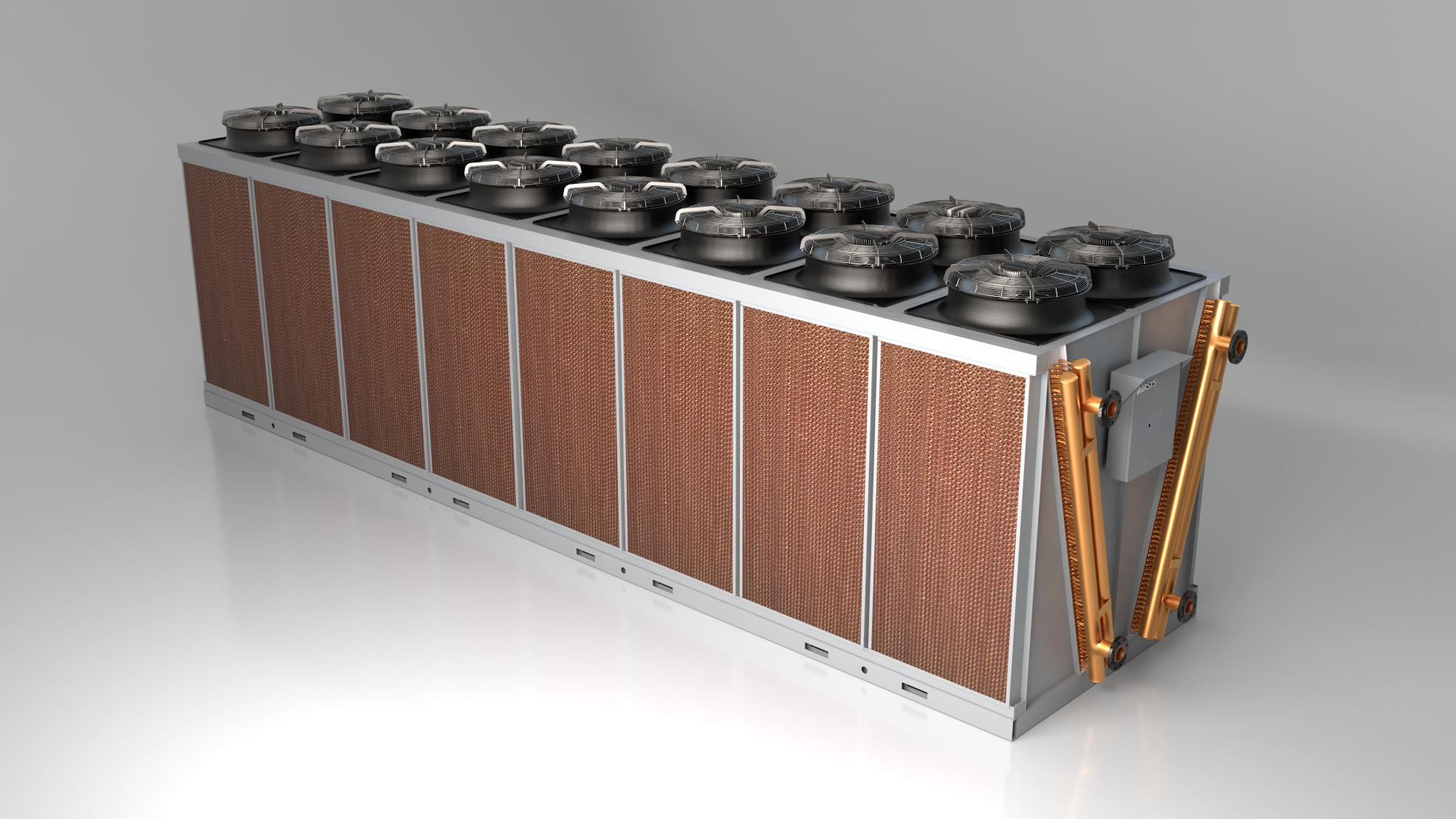
Published constructionAir-cooled dry cooler with adiabatic evaporative assistanceOfficial family description; coil/spray circuit details and actual fluid interface not provided. Source
Family capacity statement100–1,400 kWUnconditioned family span, not a rated selected unit or constant capacity across ambient conditions. Source
Outdoor temperature statement−25 to +50 °CManufacturer page; selected capacity, frost protection and mode limits not specified. Source
Protection / fansIPX4 page entry; EC fans and enlarged heat-exchange coilsSupplier construction/protection statements; no current exact-model test or installed assembly protection verified. Source
Controls and groupingPLC; standard Modbus wording; group control up to 16 unitsNo protocol transport, point list or common-dependency/availability design supplied. Source
Parameters and source limits · EXCOOL

Swipe the table, or focus it and use arrow keys, to read conditions and sources.

Manufacturer-published information · EXCOOL
ParameterPublished valueConditions and evidence
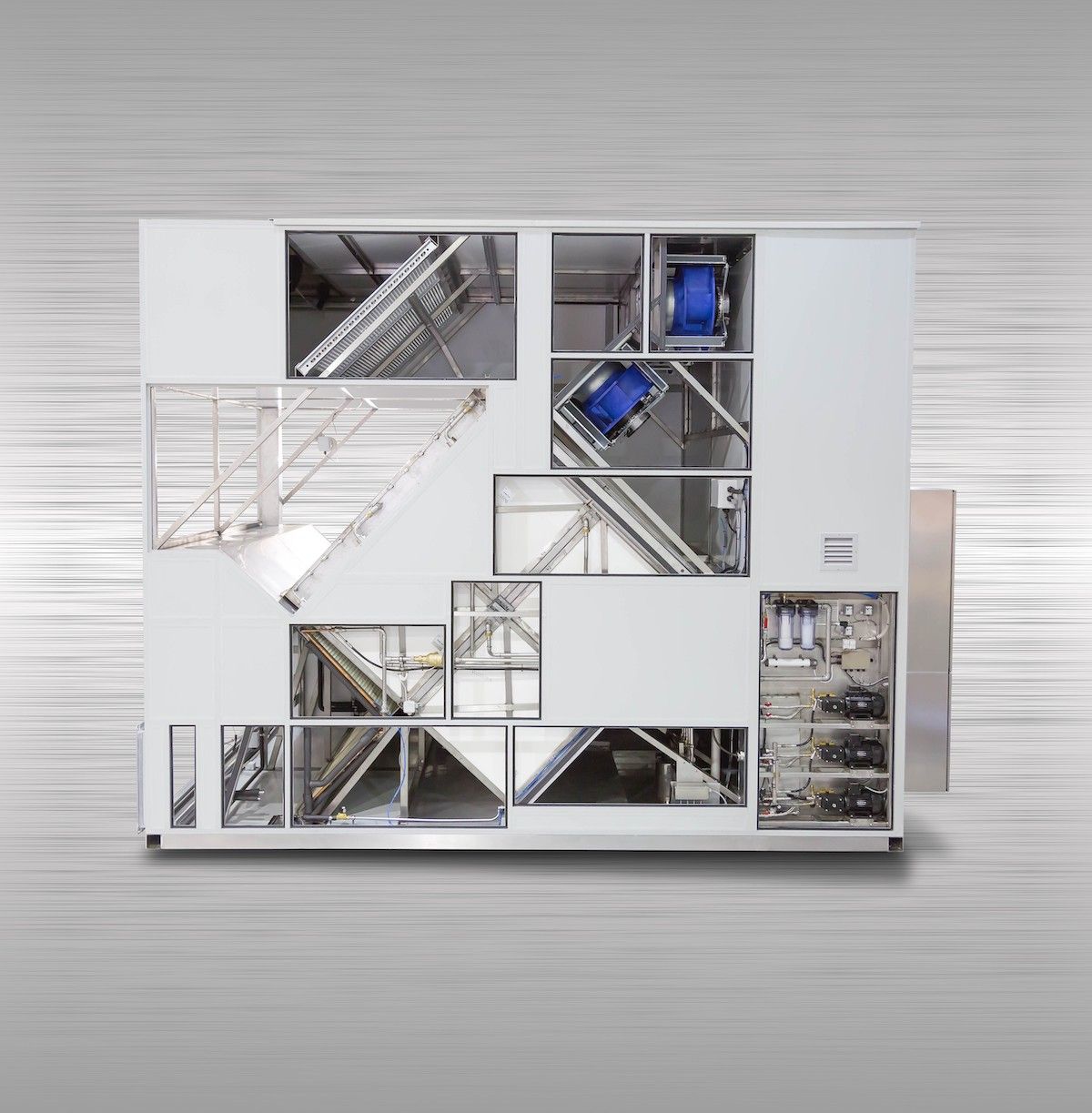
Cooling processIndirect evaporation across separated primary/secondary air streamsManufacturer's process description; actual leakage, pressure relationships and hall air conditions require a selected design. Source
Exchanger / unit materialsPolymer heat-exchange core; welded stainless-steel unit constructionPublished descriptions; grades, details and allowed chemical exposure not provided. Source
Water arrangementsHigh-pressure mist and recirculating-water spray with separate pipeworkSupplier says the systems can run independently and provide backup; no complete common-dependency diagram reviewed. Source
Drainage conceptDrain pump plus high-water-level overflow structurePublished construction; drainage capacity, discharge connection and failure response need project documents. Source
System efficiency claimWebsite markets data-centre cooling-system pPUE below 1.2Supplier statement without a buyer-specific measurement boundary, weather/load calculation or verified site result. Source
Parameters and source limits · TELECOOL

Swipe the table, or focus it and use arrow keys, to read conditions and sources.

Manufacturer-published information · TELECOOL
ParameterPublished valueConditions and evidence
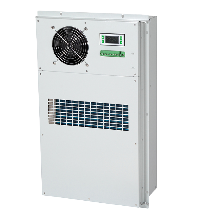
AC example: ACA010EA1220 VAC ±15%, 50 Hz; 1,000 W cooling and 410 W consumption at L35/L35PDF page 2 AC table; not an outdoor-design-day selection or a DC version. Source
DC example: ACA010ED1−48 VDC; 1,000 W cooling and 280 W consumption at L35/L35PDF page 3 DC table; voltage operating tolerance and full curve not supplied. Source
Heat-exchanger example: ACE010ED1−48 VDC; 100 W/K; 129 W consumption; 850 m³/h airflowPDF page 3 exchanger table. W/K is not watts of rated refrigeration capacity; the L35/L35 table label needs clarification. Source
Air-conditioning temperature rowsWorking −15 to 55 °C; separate 'application' −40 to 70 °CAC/DC sample tables; webpage instead prints outdoor operation −40 to 55 °C. Meaning/version must be resolved. Source
Air-conditioning constructionEmbedded mounting; R134a; IP55 table entryAC/DC brochure entries; installed-cabinet seal, cut-out and current conformity scope require separate confirmation. Source
Published control interfaceDry-contact alarms; AC section names RS485 Modbus RTUActual protocol/card on each chosen version and alarm/fail states remain to be specified. Source
Parameters and source limits · UNICOOL

Swipe the table, or focus it and use arrow keys, to read conditions and sources.

Manufacturer-published information · UNICOOL
ParameterPublished valueConditions and evidence
Actual reviewed revisionCover: UNICOOL E2011V01.2; download label: V01.3Revision difference retained for supplier clarification; filename is not treated as controlling revision. Source
50 Hz model exampleUNI.7V1B2; 230 V / 1-phase / 50 Hz; 7.2 kW total and 6.0 kW sensible rated coolingPage 20, 95 °F outdoor / 80–67 °F indoor dry–wet bulb; one model/electrical version. Source
Same example electrical schedule2.17 kW rated input; 5.6 kW maximum input; 9.4 A rated currentDifferent schedule entries; maximum/rated input are not interchangeable or independently measured here. Source
Same example free-cooling entry9.1 kW at indoor–outdoor ΔT 21.6 °FSeparate free-cooling condition; table footnote calls the function optional while feature text describes it as standard. Source
Standard versus extended ambientSelection page: standard −30 to 46 °C, up to 53 °C; storage −40 to 70 °COptional wider-envelope entries and broader prose require exact supplied configuration; storage is not operation. Source
Parameters and source limits · 20F2A2

Swipe the table, or focus it and use arrow keys, to read conditions and sources.

Manufacturer-published information · 20F2A2
ParameterPublished valueConditions and evidence
Selected catalogue example20F2A2; downflow (DN); two EC centrifugal supply fansOriginal table and configuration code, not a project selection or the only possible supply arrangement. Source
Adiabatic reference capacity34 kW; indoor 25 °C; outdoor 30 °C dry bulb / 30% RHExact table footnote; capacity is explicitly dependent on inlet air temperature and humidity. Source
Free-cooling reference32.2 kW at a 5 °C indoor/outdoor temperature differenceDifferent condition from the 34 kW adiabatic row, not one guaranteed joint duty. Source
Air and water schedule18,000 m³/h; water consumption 90.9 kg/h; pump circulation 1,500 kg/hConsumption and pump flow are separate printed rows; make-up quality, purge and site water use require a design. Source
Assembled envelope / input1,900 × 1,056 × 2,460 mm; 575 kg; 400 V / 3-phase / 50 Hz; 4.8 kW maximum operating inputAssembled main unit plus fan section. Packaged component dimensions and weights differ. Source
Parameters and source limits · VENUS-CS10LT

Swipe the table, or focus it and use arrow keys, to read conditions and sources.

Manufacturer-published information · VENUS-CS10LT
ParameterPublished valueConditions and evidence
Table operating range / accuracy−40 to +50 °C; ±0.1 °COriginal PDF page 3 right-hand CS10LT table; conflicting −80 °C diagram callout remains unresolved. Source
Low-temperature cooling point5,000 W at −30 °COne printed reference point, not capacity at every temperature or a pull-down guarantee. Source
Hydraulic referenceMaximum 30 L/min, 0.8 MPa at −30 °CNo full pump curve or simultaneous-point confirmation supplied. Source
Separate circuit mediaHFE-7200 transfer fluid; 'Mixed Refrigerant' refrigeration fieldNamed fluid and unspecified refrigerant mixture; current formulation, materials and service documents need confirmation. Source
Envelope / power schedule500 × 1,000 × 1,700 mm W×D×H; 200–220 VAC, 3-phase, 50/60 Hz; 20.4 kVA inputApparent-power entry with 75 A breaker wording, not 20.4 kW measured consumption or a complete electrical design. Source
Parameters and source limits · VENUS-EHS306

Swipe the table, or focus it and use arrow keys, to read conditions and sources.

Manufacturer-published information · VENUS-EHS306
ParameterPublished valueConditions and evidence
Table temperature and cooling point+30 to 90 °C; 6,000 W at +50 °CC1810V01.1 EHS306 table; not a constant capacity across the full range. Source
Control accuracy±0.1 °C in the model tableMeasurement location, dynamic load and acceptance duration not stated; nearby valve callout is a separate item. Source
Heat-transfer fluid / refrigerantFC-3283 / N/AOriginal separate fields. External cooling service and current fluid supply require clarification. Source
Hydraulic row / heatingMaximum 25 L/min, 0.5 MPa at +60 °C; heaters 2.5 kW × 2Table maxima without a selected pump curve; heating rating is separate from cooling duty. Source
Envelope and electrical entry300 × 900 × 1,200 mm W×D×H; 200–220 VAC, 3-phase, 50/60 Hz; 6.75 kW inputBrochure's nominal schedule; final connectors, protection, access and external services not shown. Source
Parameters and source limits · VENUS-GTS06

Swipe the table, or focus it and use arrow keys, to read conditions and sources.

Manufacturer-published information · VENUS-GTS06
ParameterPublished valueConditions and evidence
Model-table setpoint range−10 to +60 °CPDF page 3 left-hand model; conflicts with the inspected web page's 30–200 °C wording. Source
Cooling / accuracy table6,000 W at +20 °C; ±0.1 °CControl table; diagram separately prints ±0.01 °C, so the contractual accuracy needs clarification. Source
Thermal mediaFC-3283 transfer fluid; refrigerant N/ATable identifies the circulating fluid, not all heat-rejection interfaces or a product-wide environmental claim. Source
Published maximum hydraulic row20 L/min, 0.35 MPaNo pump curve or simultaneous operating-point confirmation provided. Source
Compact envelope / input470 × 470 × 380 mm W×D×H; 200–220 VAC, 3-phase, 50/60 Hz; 8.2 kW inputOriginal brochure table; access, mounting, heat rejection and final electrical design require further documents. Source
Parameters and source limits · VENUS-ECS05

Swipe the table, or focus it and use arrow keys, to read conditions and sources.

Manufacturer-published information · VENUS-ECS05
ParameterPublished valueConditions and evidence
Model table temperature / accuracy10 to +60 °C; ±0.1 °COriginal C1810V01.1 brochure model table; accuracy location and operating conditions require an acceptance definition. Source
Published cooling point10,000 W at +20 °CFluid-temperature condition as printed; ambient and full performance map not stated beside the table. Source
Named fluid and refrigerantFC-3283 heat-transfer fluid; R-404A refrigerantSeparate table rows; current supply and tool/material compatibility require supplier/OEM confirmation. Source
Published flow / pressureMaximum 25 L/min, 0.5 MPa at +20 °COriginal row; pump curve and whether maxima are simultaneous are not established. Source
Power and envelope200–220 VAC, 3-phase, 50/60 Hz; 8.2 kW input; 400 × 900 × 1,500 mm W×D×HBrochure example, with 30 A breaker wording; final electrical protection and service space need the current installation documents. Source
Parameters and source limits · MaxAir3

Swipe the table, or focus it and use arrow keys, to read conditions and sources.

Manufacturer-published information · MaxAir3
ParameterPublished valueConditions and evidence
One module at condition 166.1 kW total and sensible; return air 38 °C / 35% RH; water 19/35 °CBrochure page 7, condition (1); no independent test or site selection. Source
Condition 1 hydraulic point3.7 m³/h water flow; 33.5 kPa coil water pressure dropSingle-module table at condition (1); piping, header and valve losses are separate. Source
One-module air/electrical schedule15,500 m³/h; one caseless backward EC centrifugal fan; 3.3 kW maximum unit operating inputPublished table. Selected external resistance and installed airflow have not been established. Source
Published single-module envelope1,620 × 1,200 × 1,130 mm; 260 kg; 400 V / 3-phase / 50 HzBrochure dimensions and mass; installation clearance and structural design remain additional requirements. Source
Module combinations1, 4, 6 or 9 modules shownTable arrangements with differing dimensions. Multiple-unit header is stated to be supplied by the installer. Source
Parameters and source limits · MEDICOOL

Swipe the table, or focus it and use arrow keys, to read conditions and sources.

Manufacturer-published information · MEDICOOL
ParameterPublished valueConditions and evidence
Published applicationMRI, CT and other medical-equipment coolingManufacturer's intended application statement; no compatibility approval for a named imaging model reviewed. Source
Refrigeration arrangementTwo independent refrigeration systemsOfficial family description; circuit capacity, hydraulics and common components not specified. Source
Published refrigerant alternativesR410A or R134aVersion-dependent alternatives, not two interchangeable refrigerants for one unit. Source
Optional operating approachFree cooling offeredOption described for cold climates; actual eligibility, circuit and performance require selection. Source
Delivery preparationManufacturer says refrigerant charged and tested before shipmentNo serial-number factory report or project acceptance test was obtained. Source
03 / PROJECT REVIEW

Separate the contracting company, production site and selected cooling system

Start with the cooling duty and ownership of the interfaces

A telecom shelter usually needs packaged air conditioning with an outdoor-air economiser. A high-density data hall may instead use chilled-water fan walls, in-row equipment or indirect evaporative plant. Medical imaging cooling requires an agreed interface with the equipment vendor, while a semiconductor tool may require a particular transfer fluid, temperature range and chamber connection. A broad AIRSYS brand enquiry does not select any of these.

The official pages provide enough material to separate MEDICOOL, VENUS, MAXAIR, UNICOOL, FREECOOL-AD and EXCOOL. Their published capacity and temperature statements cannot be combined into a single interchangeable chiller specification.

Equipment rooms

Check sensible load, room air limits, supply arrangement and outdoor-air eligibility; identify backup and control options.

Data halls

Choose air/water interfaces and containment; establish who supplies the heat rejection, pumps, headers and supervisory control.

Process equipment

Agree the OEM's thermal/hydraulic envelope, compatible transfer fluid and acceptance points before comparing models.

What the external production report establishes

The 2016 CNIPA-hosted Intellectual Property News interview identifies the company by name, describes a partner event at its Gu'an base and reports air-conditioning performance test equipment, sheet-metal and coating production lines. It dates the base's opening to 2008 and quotes a then-reported annual capacity. This provides a dated production-history reference separate from the present website.

The interview is ten years old at this review. Its capacity, management, partners and financing are not carried forward as current verified facts. Request the present workshop entity, inspection address, process ownership, test equipment, calibration records and an order-specific factory acceptance plan. Historical news does not replace these documents.

Resolve differences between landing pages and controlled brochures

VENUS's web page describes broad temperature ranges, while its linked model tables give narrower and different ranges. The MAXAIR brochure identifies MaxAir3 and lists several capacities under distinct return-air and water temperatures. The UNICOOL download link is labelled V01.3 but the cover prints V01.2; it also separates standard outdoor conditions from extended-temperature options. These are material selection issues, not cosmetic wording differences.

Individual product briefs record the relevant conditions and conflicts. Require the supplier to confirm the currently offered revision and configuration in writing. Do not use a website update date, PDF URL or family name as proof that a particular historical sheet is the contract specification.

Treat efficiency as a system calculation

The group markets low PUE or partial PUE solutions. A fan-wall brochure also mixes PUE wording with pPUE language, and some brochures present climate-dependent examples or percentage savings. None supplies a measured result for a buyer's site. Identify the measurement boundary, IT load profile, weather file, water consumption, ancillary power, redundancy state and comparison baseline before using the figures in a business case.

For a packaged product, distinguish unit input power from cooling capacity. For a chilled-water indoor unit, add the upstream water plant and pumps. For direct evaporative cooling, include water, filters, exhaust and backup operation. A group's system offer and a single product's rating are different procurement scopes.

Obtain conformity and support documents for the delivered equipment

The MEDICOOL page makes CE, UL and quality-system statements; UNICOOL mentions AHRI, ETL and CE. The reviewed pages do not provide current issuer verification and model annexes covering every configuration. The VENUS tables call their entries design standards, which is not the same as a current product certificate. Request the actual declaration, report or listing with model, revision, applicant and factory scope.

The contact page publishes a China service line and a response statement. Overseas subsidiaries and historical brochure addresses are not an order-specific response-time agreement or confirmation of spare-part stock. Define warranty start, labour, freight, refrigerant or fluid work, remote access, site attendance and the responsible local organisation.

Prepare an enquiry that can become an acceptance schedule

Send the actual installation, load, design ambient conditions, power supply, fluid/air interfaces and redundancy requirement. Ask for the manufacturing entity, current technical revision, selected duty, dimensional and connection drawings, control point list, delivered options and the factory test scope. Use the signed selection as the basis for commissioning and handover rather than a mixture of web-page maxima.

The platform has not inspected the production base or tested these systems. The official contact email was separately recorded in private CRM; it is not displayed or used to send messages. MOQ, pricing, lead time, present capacity and current certificate coverage remain unconfirmed.

07 / TRANSPARENCY

Sources and review scope

Compiled by HVACDeck Editorial. Page review: 2026-10-11. Publications are attributed below; their statements are not independent measurements by this platform.

  1. Official AIRSYS group profileChecked 2026-10-11 · Portfolio and group manufacturing-centre statements; not an entity-by-entity factory audit.
  2. Official China contactChecked 2026-10-11 · Exact Beijing legal entity, office address and separately recorded private email.
  3. CNIPA-hosted production-history interview, 18 November 2016Checked 2026-10-11 · Full article read. Gu'an production history and reported equipment; dated news, not current inspection.
  4. Official VENUS model brochureChecked 2026-10-11 · All five PDF pages read; technical spreads visually inspected; separate Beijing and Gu'an entities listed.
  5. Official MaxAir3 technical brochureChecked 2026-10-11 · All eight pages read; capacity table visually inspected.
  6. Official MOBILECOOL-OUTDOOR pageChecked 2026-10-11 · Complete page read; standard natural-cooling and general SHR claims differ from selected PDF scope.
  7. Original M-OD C2105V01.0 catalogueChecked 2026-10-11 · Actual Chinese cover C2105V01.0. Pages 1–5, 15–18 reviewed, with page 18 visual check; supply, options, SHR and duty boundaries retained.
  8. Official DATACOOL-PACKAGE product pageChecked 2026-10-11 · Complete official page read; architecture/control statements present, no model parameter table or downloadable catalogue link found in the inspected page.
  9. Official CYBERCOOL-MOD CW/DXA family pageChecked 2026-10-11 · Separate cooling forms and optional controls reviewed; not treated as one shared rating.
  10. Original CYBERCOOL-MOD CW catalogue tableChecked 2026-10-11 · Actual cover C2104V03.5. CW method pages 2–4 and page 18 performance/footnotes read; page 18 visually checked. Humidifier unit omission retained.
  11. Official OPTIMA2 product pageChecked 2026-10-11 · Complete live page read; modular range and compressor claims kept in their source scope.
  12. OPTIMA2 E2009V01.1 original catalogueChecked 2026-10-11 · Descriptive and performance pages 1–12 and contact page 17 read. Drawing pages 13–16 contain graphical dimensions not adopted here. Model/supply, table conditions and differing control/efficiency claims retained.
  13. Official FREECOOL-HD pageChecked 2026-10-11 · Complete product description and conditional supplier claims read.
  14. Original FREECOOL-HD E1805V01.3 catalogueChecked 2026-10-11 · All ten pages read. PDF page 6 technical table visually checked; actual versus nominal airflow and DC wording versus AC supply discrepancy preserved.
  15. Official FREECOOL retrofit pageChecked 2026-10-11 · Complete live description read; direct-air method, four installation forms and unverified savings/certification statements.
  16. Original FREECOOL catalogueChecked 2026-10-11 · Actual Chinese cover C1801V02.1. All eight PDF pages read; PDF page 6 technical spread visually inspected. Layout/power options and dimensional inconsistency preserved.
  17. Official CHILLROW product pageChecked 2026-10-11 · Complete live page read. DXA components separated from chilled-water form; no exact-model capacity, dimension or sound table available on this inspected page.
  18. Official INNOVA Series MDC pageChecked 2026-10-11 · Double-row package, integrated services and general supplier claims reviewed.
  19. Original AIRSYS data-centre infrastructure catalogueChecked 2026-10-11 · Actual cover C2005V01.1. Reviewed single/double-row sections pages 7–14 and monitoring pages 37–38; page 13–14 configuration spreads visually inspected. Other portfolio tables are not adopted as INNOVA ratings.
  20. Official ADIACOOL dry-cooler pageChecked 2026-10-11 · Complete live page read. Family range, temperature/protection/group-control statements and undefined 80% claim; no selected thermal or water schedule.
  21. Official EXCOOL process and system pageChecked 2026-10-11 · Complete live page read: separated air paths, polymer core, spray/drain construction and scoped efficiency claims. No model duty table or independent performance report supplied.
  22. Official TELECOOL pageChecked 2026-10-11 · DC-only web wording and general temperature/control claims reviewed; photograph is a family illustration, not proof of an exact ACA/ACE variant.
  23. Original TELECOOL E1803V01.5 brochureChecked 2026-10-11 · All four PDF pages read; both technical spreads visually inspected. AC/DC/exchanger units, W versus W/K, and source conflicts retained.
  24. Official UNICOOL pageChecked 2026-10-11 · Live envelope and feature claims, plus V01.3 download label.
  25. Original downloaded UNICOOL brochureChecked 2026-10-11 · All 24 pages read; cover actually V01.2. Page 20 50 Hz table/footnotes visually inspected; revision, option and protocol discrepancies retained.
  26. Official FREECOOL-AD pageChecked 2026-10-11 · Live product/process description read.
  27. Original FREECOOL-AD E1805V02.1 brochureChecked 2026-10-11 · All ten PDF pages read; mode diagrams, 20F2A2 table/footnotes, optional components and dated consultancy-cover limitation reviewed.
  28. Official VENUS web descriptionChecked 2026-10-11 · EHS306 Peltier wording retained as a configuration question; no circuit inferred.
  29. Official MAXAIR pageChecked 2026-10-11 · Live page reviewed; rounded basic-module capacity and PowerOne claims.
  30. Official MEDICOOL family pageChecked 2026-10-11 · Complete live page read. Family construction, options and manufacturer conformity claims; no model capacity table.

How we review sources · Represent this factory or request a correction

Prepare your equipment brief