
AIRSYS VENUS-EHS306 heat-exchange temperature-control unit
A heat-exchange temperature-control unit tabled at +30 to 90 °C and 6 kW at +50 °C, with no refrigerant circuit listed.
From AIRSYS precision and process cooling
Product guide · HVACDeck Editorial · Sources checked 2026-10-11

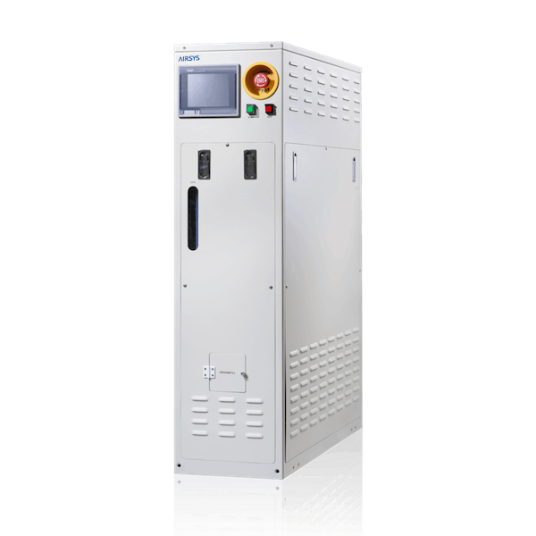
AIRSYS VENUS-EHS306: heat-exchange duty, facility services and tool fit
EHS306 is the heat-exchange-type constant-temperature liquid-cooling model in the AIRSYS VENUS brochure. Its data row lists +30 to 90 °C, 6 kW cooling at +50 °C, ±0.1 °C control accuracy, two 2.5 kW heaters and FC-3283 as the transfer fluid. The refrigerant field reads N/A. The web landing page adds a description of Peltier modules.
EHS306 serves a process tool that runs warm, and it removes heat through a facility-side service. For a quotation, send the chamber inlet temperature, load, fluid requirements and the facility cooling water or other service you can provide. Ask AIRSYS for the circuit diagram of the current configuration so you know which services the unit needs.
Published parameters and their scope
The catalogue identifies a model reference; confirm the current revision and selected options.
- Model
- VENUS-EHS306
Swipe the table, or focus it and use arrow keys, to read the conditions and sources.
| Parameter | Published value | Conditions and sources |
|---|---|---|
| Range and cooling point | +30 to 90 °C; 6,000 W at +50 °C | C1810V01.1 table; capacity varies across the range. Source |
| Control accuracy | ±0.1 °C in the model table | Agree the measuring point, load and duration. A valve callout nearby prints a separate figure. Source |
| Fluid and refrigerant | FC-3283 / N/A | Separate table fields. Ask for the facility-side service requirements. Source |
| Hydraulics and heating | Maximum 25 L/min, 0.5 MPa at +60 °C; heaters 2.5 kW × 2 | Request the pump curve; heater rating is separate from cooling duty. Source |
| Size and supply | 300 × 900 × 1,200 mm W×D×H; 200–220 VAC, 3-phase, 50/60 Hz; 6.75 kW input | Nominal brochure schedule; connectors, protection and access come with the drawings. Source |
Selection and application
How EHS306 cools
The brochure calls EHS306 heat-exchange type and lists no refrigerant, while the landing page describes Peltier cooling and heating. Ask AIRSYS for the controlled circuit diagram and a short description of the configuration it will deliver.
List every facility-side service and the boundary between unit and tool. Request the permitted service temperatures, flow, pressure, cleanliness and materials, with the capacity available under your conditions. Heat removal and auxiliary energy still have to be supplied, so plan the utility connections from that drawing.
Cooling point and flow at the right temperature
The 6 kW figure is printed at +50 °C and the maximum-flow row at +60 °C. Ask for one thermal and hydraulic schedule at your actual tool inlet temperature, with FC-3283 properties and the facility conditions used.
The 25 L/min and 0.5 MPa values come without a pump curve. Request the tool-side pressure limits, flow control method and a loss calculation for your piping and manifold. The brochure says a two-channel configuration may be offered; if you need it, ask for capacity per channel and the parts both channels share.
Temperature response and heating
The table states ±0.1 °C; the artwork labels a precision three-way valve with ±0.01 wording. Set the acceptance sensor, its location and calibration, the setpoint, allowed excursions and the tool's load sequence in the test plan.
The heaters are 2.5 kW × 2 with a printed surface-loading figure. Ask which heating circuits are fitted and how the unit moves between heating and cooling at your load, including warm-up time and continued flow during mode changes.
Fluid, connections and bay space
Get the approved materials and connectors for the tool, the supplied fluid quantity, fill volume, preparation and maintenance guidance for FC-3283. The process-equipment vendor should confirm compatibility and permitted pressure.
At 300 mm wide the enclosure is slim, but connections, isolation valves and removable parts still need room. Request the general arrangement, service access drawing, mounting instructions and the space for hoses and utilities, and plan the full bay from those.
Integration and test documents
The brochure lists Analog, Digital and Serial interfaces, transient-power protection, and it cites CE, S-Mark and Semi-S2 for design. Order the tool-specific protocol map, wiring and fault and interlock schedule with the unit, along with current conformity documents.
Run factory acceptance with the approved fluid, the selected facility services, the agreed thermal duty and load transitions and the tool integrator's alarm and enable signals. The test record should name the producing company and document revision.
Get these EHS306 answers in writing
Ask AIRSYS to confirm: the cooling method and circuit diagram; facility service temperatures, flow and quality; capacity and flow at your inlet temperature; the meaning of ±0.1 °C and the valve callout; heater circuits fitted; FC-3283 supply; installed footprint with service space; protocol and point map; conformity documents; and availability, price and warranty.
Sources
Compiled by HVACDeck Editorial. Figures are as published by the manufacturer; ask for test records for the unit you select.
- Official VENUS web descriptionChecked 2026-10-11 · Family text including the Peltier cooling and heating wording.
- Official VENUS C1810V01.1 brochureChecked 2026-10-11 · EHS306 model table and valve callout: range, cooling point, fluid, heaters, hydraulics, size and supply.
Editorial method and corrections · Report a detail with this page URL
Send an enquiry
Send the manufacturer your required duty, installation conditions and the points listed above to confirm.
Continue the selection
Other equipment from this manufacturer
AIRSYS MOBILECOOL-OUTDOOR wall-mounted telecom cooling
AIRSYS DATACOOL-PACKAGE integrated room cooling
AIRSYS CYBERCOOL-MOD CW chilled-water room terminals
AIRSYS CYBERCOOL-MOD DXA air-cooled room cooling