
AIRSYS VENUS-GTS06 thermoelectric temperature-control unit
A compact thermoelectric model with a −10 to 60 °C table; its web page instead describes 30 to 200 °C, and the diagram's precision wording differs from the table.
From AIRSYS precision and process cooling
Individual product research · HVACDeck Editorial · Sources checked 2026-10-11

Qualify the GTS06 setpoint, stability and heat-removal interface
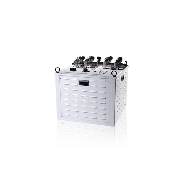
AIRSYS's VENUS brochure labels GTS06 a thermoelectric constant-temperature liquid-cooling unit. The PDF model table gives −10 to +60 °C, 6,000 W at +20 °C and ±0.1 °C control accuracy. The same spread describes thermoelectric modules and a compact assembly intended to sit near the process chamber; the refrigerant row is N/A and the named circulating fluid is FC-3283.
The official web page instead assigns 30 to 200 °C to GTS06. A diagram callout in the PDF also uses ±0.01 °C while its parameter table uses ±0.1 °C. Neither conflict has been resolved by a current supplier document. This review records the model table and the differences rather than selecting the most attractive range or precision figure.
Published parameters and their scope
The catalogue identifies a model reference; confirm the current revision and selected options.
- Model
- VENUS-GTS06
Swipe the table, or focus it and use arrow keys, to read the conditions and sources.
| Parameter | Published value | Conditions and evidence |
|---|---|---|
| Model-table setpoint range | −10 to +60 °C | PDF page 3 left-hand model; conflicts with the inspected web page's 30–200 °C wording. Source |
| Cooling / accuracy table | 6,000 W at +20 °C; ±0.1 °C | Control table; diagram separately prints ±0.01 °C, so the contractual accuracy needs clarification. Source |
| Thermal media | FC-3283 transfer fluid; refrigerant N/A | Table identifies the circulating fluid, not all heat-rejection interfaces or a product-wide environmental claim. Source |
| Published maximum hydraulic row | 20 L/min, 0.35 MPa | No pump curve or simultaneous operating-point confirmation provided. Source |
| Compact envelope / input | 470 × 470 × 380 mm W×D×H; 200–220 VAC, 3-phase, 50/60 Hz; 8.2 kW input | Original brochure table; access, mounting, heat rejection and final electrical design require further documents. Source |
Selection and application review
Resolve the 200 °C statement before selecting this model
A buyer looking for high-temperature CVD/PVD/etch temperature control could be misled by the GTS06 web paragraph. The linked model table's upper value is +60 °C, and its lower value is −10 °C. Request a controlled current model sheet identifying whether the website describes another configuration or contains an error. Until then, this model is not established here as a 200 °C unit.
Provide the tool's steady-state and transient temperature requirements and ask for a selected capacity throughout that envelope. A 6 kW point at +20 °C does not establish 6 kW at either temperature limit or under another heat-rejection condition.
Separate control accuracy from the diagram callout
The left-hand spread's parameter table gives ±0.1 °C, while a nearby callout describes rapid response and ±0.01 °C. This review does not reinterpret the latter as verified outlet stability, sensor resolution or process accuracy. Ask AIRSYS to define each figure and the measurement conditions.
Specify the acceptance sensor location, calibration, fluid volume, tool load steps and permitted settling/overshoot. The nearby-chamber concept may change piping length and volume, but the brochure supplies no actual layout or tested response trace for the buyer's tool. A signed test plan should connect the required behaviour to the delivered configuration.
Ask where the thermoelectric system rejects its heat
The brochure describes thermoelectric modules, an IGBT/SMPS circuit and a DC variable-speed liquid pump. The N/A refrigerant entry does not identify the complete heat-rejection service or remove the need for an energy/thermal balance. Obtain the circuit diagram, external service requirements and permitted interface temperatures and flows.
Confirm FC-3283 compatibility with the tool and wetted parts, the fill volume, connectors and fluid preparation. Ask for the actual pump curve at the working temperature and the allowed pressure at the tool. Do not pair the printed 20 L/min and 0.35 MPa maxima into a guaranteed point without the selection.
Check bay integration and electrical load
The 470 × 470 × 380 mm assembly is described as compact enough to locate near a chamber. Establish support, vibration, connectors, removal direction and space around service connections using a current drawing. The envelope alone does not establish that it fits a particular tool or can be maintained in the proposed bay.
The table's 8.2 kW input is distinct from its 6 kW cooling point. Require the electrical schedule, protective-device instructions, mode-dependent consumption and any auxiliary service loads. The brochure's 30 A breaker entry is not a complete project electrical design or proof that all variants use the same supply.
Agree the communications and failure response
Analog/Digital/Serial is the published interface description. It does not establish the actual protocol, tool controller compatibility, commands, status, alarm map or safe response to lost communication. Request these documents and identify the division of control responsibility between the temperature unit and process tool.
The brochure claims transient-power protection and lists CE, S-Mark and Semi-S2 as design standards. Current conformity coverage, recovery behaviour and availability need unit-specific evidence. Include the agreed thermal stability, selected flow/pressure, alarms, interlocks and communication-loss response in factory acceptance; the platform has not tested the system or qualified a semiconductor process.
Sources and review scope
Compiled by HVACDeck Editorial. Source review identifies what the publication states; it is not an independent performance test or certification.
- Official VENUS web pageChecked 2026-10-11 · GTS06 30–200 °C description recorded as a conflict, not adopted as verified rating.
- Original VENUS model brochureChecked 2026-10-11 · PDF page 3 left-hand GTS06 table and callouts visually inspected; all five PDF pages read.
Editorial method and corrections · Report a detail with this page URL
Turn the evidence into an enquiry
Send the manufacturer your required duty, installation conditions and the unresolved items identified in this brief.
Continue the selection
Other equipment from this manufacturer
AIRSYS MOBILECOOL-OUTDOOR wall-mounted telecom cooling
AIRSYS DATACOOL-PACKAGE integrated room cooling
AIRSYS CYBERCOOL-MOD CW chilled-water room terminals
AIRSYS CYBERCOOL-MOD DXA air-cooled room cooling