
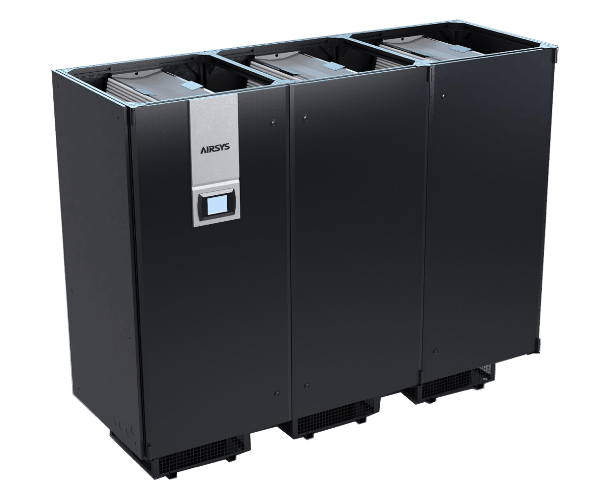
AIRSYS CYBERCOOL-MOD CW chilled-water room terminals
A modular chilled-water room unit whose usable sensible duty depends on return air, water temperatures, flow, valve loss and the actual raised-floor air path.
From AIRSYS precision and process cooling
Individual product research · HVACDeck Editorial · Sources checked 2026-10-11

Close CYBERCOOL-MOD CW's hydraulic and air-distribution duty
The CW version of CYBERCOOL-MOD uses a site-provided chilled-water plant to carry equipment-room heat away through its coil. It does not require the DXA family's separate air-cooled condenser, compressor or refrigerant-pump economiser. The original C2104V03.5 catalogue supplies a separate CW table, so DX condenser performance and electrical figures should not be copied into this product.
The 100X2 example gives 107.0 kW total and 95.9 kW sensible at return 24 °C/50% RH with 7/12 °C entering/leaving water, requiring 18.0 m³/h and 55.8 kPa across coil plus valve. A second rating uses different return air and 10/15 °C water. Those complete condition sets are the basis for comparing offers and pump interfaces, rather than one family maximum.
Published parameters and their scope
This is an equipment family; its range does not identify one orderable configuration.
- Family designation
- CYBERCOOL-MOD CW
Swipe the table, or focus it and use arrow keys, to read the conditions and sources.
| Parameter | Published value | Conditions and evidence |
|---|---|---|
| 100X2 rating set A | 107.0 kW total / 95.9 kW sensible; return 24 °C, 50% RH; water 7/12 °C | Original PDF page 18 CW table, footnote 2. Source |
| 100X2 hydraulics at set A | 18.0 m³/h; 55.8 kPa coil plus valve pressure drop | Same rating basis. This pressure drop does not include all site piping, strainers and fittings. Source |
| 100X2 rating set B | 103.1 kW total / 102.1 kW sensible; return 28 °C, 40% RH; water 10/15 °C | Footnote 3 changes both air and water; not a water-only comparison. Source |
| 100X2 air movement | Two EC backward-curved fans; 25,000 m³/h; O/U supply | Catalogue table. Downflow fans must descend below the raised floor per its explicit footnote. Source |
| 100X2 power and size | 380 V / 3Ph / 50 Hz; 22.0 kW maximum operating power; 1,880 W × 990 D × 1,975 H mm; 560 kg | Includes source maximum entry rather than measured fan energy; actual configuration/support need approval. Source |
Selection and application review
Select the coil at one complete air and water condition
Provide the room sensible load, return air temperature/humidity, permitted supply conditions and available chilled-water temperatures. Ask for selected total and sensible output, flow and pressure drop at that same basis. The two 100X2 table sets change both return air and water temperature; their difference cannot isolate the effect of warmer water.
A high sensible fraction under one rating does not remove condensate or humidity-management requirements under every condition. Have the room designer close coil operation, condensation, drains, insulation and control set points against the intended environment. The platform has not tested either published rating.
Coordinate valve loss, pump pressure and actual site pipework
The 55.8 kPa example includes coil plus valve. Add site supply/return pipe, strainers, isolation, balancing and other losses in the hydraulic design rather than using the catalogue figure as the entire pump requirement. Obtain a current unit hydraulic schematic and valve schedule; the website lists PICV as an option, so do not assume a particular valve is delivered.
The CW table describes standard lower welded connections. Require the ordered connection positions/sizes and permitted flow/pressure/water-quality range, plus flushing and maintenance instructions. Define how the terminal behaves with unavailable water, low flow or valve/control failure and how the central plant covers the required remaining load.
Reserve space below the floor for the downflow arrangement
The table explicitly says downflow fans need to descend beneath the raised floor. Coordinate plenum depth, obstructions, cable trays, pedestals, supports and removal routes before approving a cabinet drawing. The 1,975 mm cabinet height by itself does not establish the full installed height or service envelope.
Obtain delivered airflow at the selected external resistance and filter loading. Room pressure control is listed as an option on the web page; specify actual sensors, logic and the rack/room air path. A catalogue volume does not prove acceptable temperatures at every rack inlet.
Approve the supply route
Choose upflow or downflow and coordinate the actual room/floor air path.
Approve the installed envelope
Include fan descent, supports and removal access instead of only cabinet height.
Check room delivery
Select airflow at installed resistance and agree measured commissioning points.
Separate central-plant energy and availability from the terminal
The CW unit relies on central chilled water. Fan/terminal performance is not the complete cooling-system EER or data-centre PUE; account for plant, pumps, terminal auxiliaries and the relevant operating mode. DX condenser or refrigerant-pump figures from another variant do not apply to this coil terminal.
Similarly, module expansion and multiple fans do not by themselves establish independent cooling paths. Obtain the plant, water, electrical and controls dependency design with selected remaining duty during maintenance or failure. Require the exact delivered control/software and point map for group monitoring.
Confirm included heat, humidity equipment and the current issued schedule
For 100X2 the source lists a default 9 kW heater and an electrode humidifier quantity entry of 8; the humidifier row omits its unit in this table. No inferred unit is added here. Ask for an explicit current humidifier schedule and include its water, drain and power requirements only if ordered. Confirm filtration and maintenance access with the selected assembly.
The live download label says C2104V03.6, while the inspected cover says C2104V03.5. Obtain the current issued offer before committing dimensions or performance. A useful acceptance package closes hydraulic/air duty, option list, alarms, current conformity documents and commissioning results; no certification, stock, installed efficiency or warranty coverage has been independently established by this platform.
Sources and review scope
Compiled by HVACDeck Editorial. Source review identifies what the publication states; it is not an independent performance test or certification.
- Official CYBERCOOL-MOD CW/DXA family pageChecked 2026-10-11 · Separate cooling forms and optional controls reviewed; not treated as one shared rating.
- Original CYBERCOOL-MOD CW catalogue tableChecked 2026-10-11 · Actual cover C2104V03.5. CW method pages 2–4 and page 18 performance/footnotes read; page 18 visually checked. Humidifier unit omission retained.
Editorial method and corrections · Report a detail with this page URL
Turn the evidence into an enquiry
Send the manufacturer your required duty, installation conditions and the unresolved items identified in this brief.
Continue the selection
Other equipment from this manufacturer
AIRSYS MOBILECOOL-OUTDOOR wall-mounted telecom cooling
AIRSYS DATACOOL-PACKAGE integrated room cooling
AIRSYS CYBERCOOL-MOD DXA air-cooled room cooling
AIRSYS OPTIMA2 modular precision cooling