
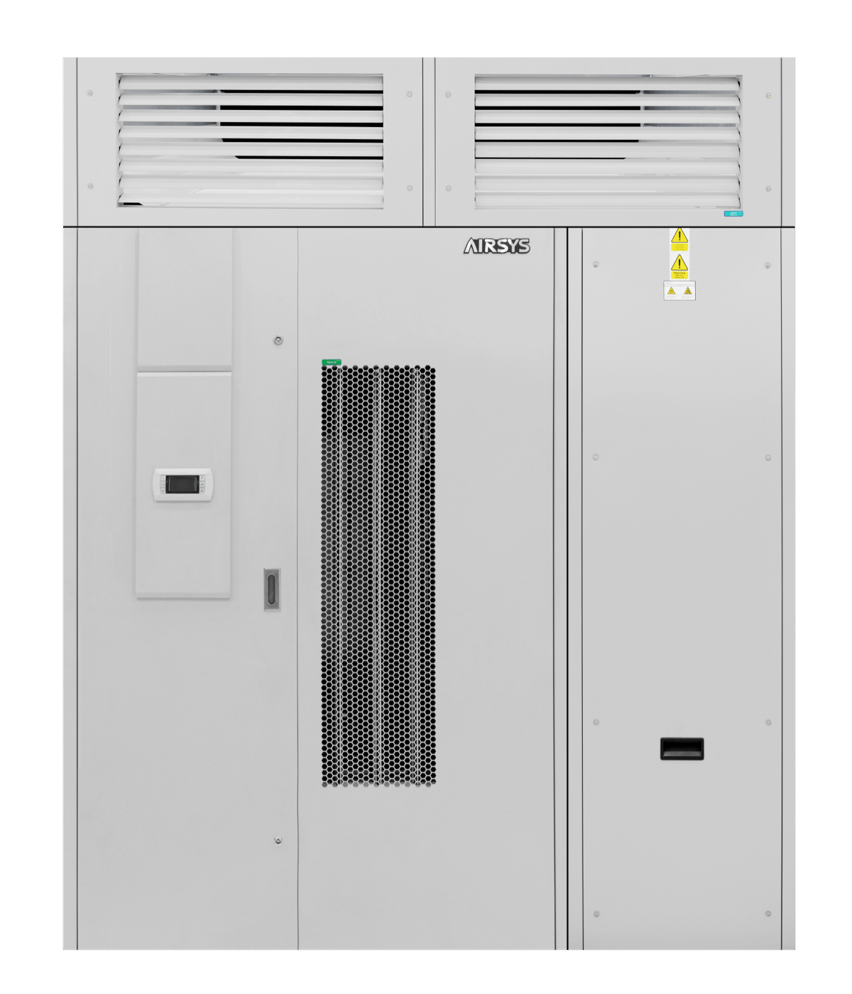
AIRSYS FREECOOL-AD 20F2A2 direct evaporative cooling
An 18,000 m³/h direct outside-air unit with a 34 kW conditional example; climate, humidity, exhaust and water services determine whether the installation can use it.
From AIRSYS precision and process cooling
Individual product research · HVACDeck Editorial · Sources checked 2026-10-11

Test the FREECOOL-AD air and water design against the site's climate
AIRSYS FREECOOL-AD uses a wetted evaporative pad to cool outdoor air before delivering it into an IT space. Its linked E1805V02.1 brochure distinguishes ordinary free cooling, direct adiabatic evaporation and extreme-cold operation with warm return-air mixing. This air path is different from EXCOOL's separated primary/secondary air streams: the FREECOOL-AD supply includes outside air and its moisture condition is part of the selection.
The reviewed 20F2A2 table gives 18,000 m³/h and 34 kW cooling in adiabatic mode at indoor 25 °C, outdoor 30 °C dry bulb and 30% RH. Its 32.2 kW free-cooling entry instead uses a 5 °C indoor/outdoor temperature difference. Those two reference conditions must remain attached to their capacities. The brochure's broad energy-saving comparisons do not establish performance in the buyer's climate or room.
Published parameters and their scope
The catalogue identifies a model reference; confirm the current revision and selected options.
- Model
- 20F2A2
Swipe the table, or focus it and use arrow keys, to read the conditions and sources.
| Parameter | Published value | Conditions and evidence |
|---|---|---|
| Selected catalogue example | 20F2A2; downflow (DN); two EC centrifugal supply fans | Original table and configuration code, not a project selection or the only possible supply arrangement. Source |
| Adiabatic reference capacity | 34 kW; indoor 25 °C; outdoor 30 °C dry bulb / 30% RH | Exact table footnote; capacity is explicitly dependent on inlet air temperature and humidity. Source |
| Free-cooling reference | 32.2 kW at a 5 °C indoor/outdoor temperature difference | Different condition from the 34 kW adiabatic row, not one guaranteed joint duty. Source |
| Air and water schedule | 18,000 m³/h; water consumption 90.9 kg/h; pump circulation 1,500 kg/h | Consumption and pump flow are separate printed rows; make-up quality, purge and site water use require a design. Source |
| Assembled envelope / input | 1,900 × 1,056 × 2,460 mm; 575 kg; 400 V / 3-phase / 50 Hz; 4.8 kW maximum operating input | Assembled main unit plus fan section. Packaged component dimensions and weights differ. Source |
Selection and application review
Choose the outdoor-air conditions before relying on capacity
The catalogue's 34 kW example uses dry outdoor air at 30 °C and 30% RH. The evaporative process changes the supplied air's moisture condition; a humid design day is a different selection. Obtain the weather/load analysis, permitted IT inlet envelope and supply condition in each mode. The original brochure refers to a 2015 industry-guideline edition, which is not a current universal permission for the buyer's equipment.
Request operating limits, mode transitions and the contribution of conventional backup cooling under conditions where outdoor air cannot meet the required temperature/humidity. The manufacturer's 'up to 90%' saving and global scenarios are not an unconditional project guarantee. Specify the comparison equipment, load profile, climate input and auxiliary power for any calculation.
Complete the supply, return and exhaust paths
The 20F2A2 table identifies downflow, while the brochure describes a separate supply box allowing top/bottom arrangements. Approve the actual configuration and connection drawing. Since outside air enters the room, identify the exhaust or pressure-relief route, room pressure control and how return air is mixed in the extreme-cold mode. The optional exhaust fan and gravity relief valve are not automatically included.
The printed airflow is not an installed result after filters, ducts, louvres and terminals. Obtain available external pressure and the chosen fan point for the complete air path. Include dirty-filter and stopped-component conditions, and agree the installed airflow and pressure measurements at commissioning.
Distinguish water consumption from circulation and purge
The table's 90.9 kg/h consumption and 1,500 kg/h pump flow describe different things. Obtain the project's make-up, drain and purge schedule at the selected climate/load, as well as inlet water pressure and quality limits. Do not use circulation as purchased-water demand or assume the consumption value covers every operating hour.
The brochure describes float switches, water-level control, leakage sensing, scale-related draining and pad drying. It reproduces the cover of a consultancy report dated 24 September 2015, but not the complete evaluation findings. This review does not treat that cover or the supplier's measures as a current hygiene certification or assurance of safe site operation. Request the actual evaluation, current maintenance requirements and the site's competent water-system assessment.
Separate installed weight from shipping sections
The unit is split into a main section and a fan section. The table lists an assembled height of 2,460 mm and weight of 575 kg; it also lists separate unpacked and packaged dimensions/weights. Select transport, lifting and support using the applicable drawings and piece weights. The assembled envelope is not the size of either packaged shipment.
Most listed maintenance is at the front, but access to pads, fan, water tray, filter and controls still needs a service-space drawing. Confirm standard inland corrosion treatment versus optional sea-air treatment for the actual location. Supplier life-cycle wording is not an order-specific corrosion warranty.
Specify controls and interlocks as deliverables
The brochure describes humidity inhibition, temperature sensors, filter differential pressure, water-level switches, automatic alarms and delayed random restart after power recovery. Communications cards, pCOWeb, external leakage and smoke/fire alarms are listed as options; request an explicit included/optional schedule. Obtain the current point map, protocol, mode sequence and fail-state behaviour.
Agree the interaction with existing mechanical cooling and the response when humidity, air contamination, water supply or a component prevents outdoor-air operation. Supplier performance comparisons and a historical evaluation cover do not substitute a witnessed functional test. Current product revision, water demand, installed duty, price and warranty require a project selection and quotation.
Sources and review scope
Compiled by HVACDeck Editorial. Source review identifies what the publication states; it is not an independent performance test or certification.
- Official FREECOOL-AD pageChecked 2026-10-11 · Live product/process description read.
- Original FREECOOL-AD E1805V02.1 brochureChecked 2026-10-11 · All ten PDF pages read; mode diagrams, 20F2A2 table/footnotes, optional components and dated consultancy-cover limitation reviewed.
Editorial method and corrections · Report a detail with this page URL
Turn the evidence into an enquiry
Send the manufacturer your required duty, installation conditions and the unresolved items identified in this brief.
Continue the selection
Other equipment from this manufacturer
AIRSYS MOBILECOOL-OUTDOOR wall-mounted telecom cooling
AIRSYS DATACOOL-PACKAGE integrated room cooling
AIRSYS CYBERCOOL-MOD CW chilled-water room terminals
AIRSYS CYBERCOOL-MOD DXA air-cooled room cooling