
AIRSYS VENUS-CS10LT low-temperature process chiller
A low-temperature model documented in the linked brochure: −40 to +50 °C and 5 kW at −30 °C, with a contradictory −80 °C illustration callout.
From AIRSYS precision and process cooling
Individual product research · HVACDeck Editorial · Sources checked 2026-10-11

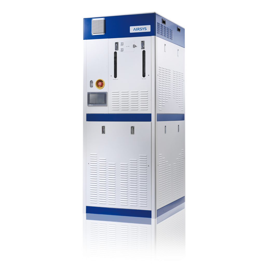
Select CS10LT at the required low-temperature duty and recovery profile
VENUS-CS10LT appears in AIRSYS's linked model brochure as a low-temperature constant-temperature liquid-cooling unit. Its table specifies −40 to +50 °C, ±0.1 °C control accuracy, 5,000 W cooling at −30 °C and HFE-7200 transfer fluid. The refrigeration field is 'Mixed Refrigerant', without a composition or charge. Unlike the other models on the web landing page, this model's usable schedule is in the brochure.
The same illustration claims rapid cooling from 20 to −80 °C in ten minutes, which goes beyond the table's −40 °C lower limit. No load, fluid volume or external conditions accompany that callout. This brief does not adopt it as the model's rated envelope or a promised pull-down time. Require a current supplier selection covering the actual steady-state and transient duty.
Published parameters and their scope
The catalogue identifies a model reference; confirm the current revision and selected options.
- Model
- VENUS-CS10LT
Swipe the table, or focus it and use arrow keys, to read the conditions and sources.
| Parameter | Published value | Conditions and evidence |
|---|---|---|
| Table operating range / accuracy | −40 to +50 °C; ±0.1 °C | Original PDF page 3 right-hand CS10LT table; conflicting −80 °C diagram callout remains unresolved. Source |
| Low-temperature cooling point | 5,000 W at −30 °C | One printed reference point, not capacity at every temperature or a pull-down guarantee. Source |
| Hydraulic reference | Maximum 30 L/min, 0.8 MPa at −30 °C | No full pump curve or simultaneous-point confirmation supplied. Source |
| Separate circuit media | HFE-7200 transfer fluid; 'Mixed Refrigerant' refrigeration field | Named fluid and unspecified refrigerant mixture; current formulation, materials and service documents need confirmation. Source |
| Envelope / power schedule | 500 × 1,000 × 1,700 mm W×D×H; 200–220 VAC, 3-phase, 50/60 Hz; 20.4 kVA input | Apparent-power entry with 75 A breaker wording, not 20.4 kW measured consumption or a complete electrical design. Source |
Selection and application review
Resolve the lower limit before accepting a pull-down claim
The parameter table stops at −40 °C, whereas the illustrated rapid-cooling statement reaches −80 °C. Do not broaden the approved envelope or promise a ten-minute pull-down by using the diagram alone. Ask for the correct model/revision, the permitted continuous range and the exact test behind the transient statement.
A useful selection states the starting temperature, target, fluid volume, tool/piping thermal mass, applied load and ambient/heat-rejection conditions. Separate no-load pull-down from loaded process recovery. The single 5 kW point at −30 °C does not answer those questions.
Request the low-temperature thermal and pump maps
Cooling capacity and the maximum-flow row both reference −30 °C, but no pump/performance map is shown. Obtain the available capacity and flow/pressure at each required setpoint using the approved fluid properties. Confirm the minimum flow, pressure controls and the process tool's allowable inlet pressure rather than assuming 30 L/min at 0.8 MPa.
Include the actual hose, manifold and tool losses in the hydraulic selection. The brochure's special low-temperature-system and component claims identify design intent; they do not supply a measured operating point for the buyer's loop. If multiple tool channels are proposed, require a channel-level selection and isolation scheme.
Close fluid, refrigerant and low-temperature connections
The table names HFE-7200 in the transfer-fluid circuit and describes the refrigeration side only as a mixture. Request the current fluid and refrigerant documents, charge/fill scope, material compatibility, maintenance information and the approved pressure/temperature ratings of connections. The platform does not invent the mixture composition or substitute a different circulating fluid.
A low-temperature installation also needs the supplier and tool integrator to define insulation, condensation protection, expansion and the treatment of exposed connections. Obtain those requirements in the current installation documents. The enclosure photograph and nominal dimensions do not establish the thermal protection of a site's hoses or tool interface.
Keep apparent power separate from energy consumption
CS10LT's input is printed as 20.4 kVA, while some other VENUS tables use kW. This page preserves that distinction. Request the actual active-power/current schedule, power factor, starting behaviour and applicable protective-device instructions for the selected mode and supply. Do not use 20.4 kVA as measured 20.4 kW consumption or calculate efficiency from it.
The heating row says flange type but gives no heater capacity. Obtain its rating and the heating/cooling transition behaviour if the duty crosses the range. Approve the installation, access, lifting and service drawings for the 500 × 1,000 × 1,700 mm enclosure before allocating bay space.
Define tool communications and acceptance at cold duty
The interface field says 'Option', unlike the explicit Analog/Digital/Serial fields of other VENUS models. Identify the actual controller, protocol, point list, wiring and alarm/interlock response in the quotation. Include loss of communication and power-recovery behaviour in the tool integration review. The brochure's transient-power and vibration protection wording is not a unit-specific test result.
Use the agreed cold duty and transient profile for factory acceptance, including calibrated temperature measurement and selected flow/pressure. CE, S-Mark and Semi-S2 are printed as design standards; current conformity and serial/manufacturing records must be supplied separately. This platform has not witnessed testing or qualified a process, and price, lead time and warranty remain unconfirmed.
Sources and review scope
Compiled by HVACDeck Editorial. Source review identifies what the publication states; it is not an independent performance test or certification.
- Original official VENUS model brochureChecked 2026-10-11 · All five PDF pages read. Page 3 right-hand CS10LT table, illustration and contradictory pull-down callout visually inspected. Product image extracted unchanged from that original PDF.
Editorial method and corrections · Report a detail with this page URL
Turn the evidence into an enquiry
Send the manufacturer your required duty, installation conditions and the unresolved items identified in this brief.
Continue the selection
Other equipment from this manufacturer
AIRSYS MOBILECOOL-OUTDOOR wall-mounted telecom cooling
AIRSYS DATACOOL-PACKAGE integrated room cooling
AIRSYS CYBERCOOL-MOD CW chilled-water room terminals
AIRSYS CYBERCOOL-MOD DXA air-cooled room cooling