
ACA AC refrigeration
Example ACA010EA1: 220 VAC/50 Hz, 1,000 W cooling at the brochure's L35/L35 condition.
 HVAC & REFRIGERATION
The web page describes DC cabinet cooling, while its original sample also contains 220 VAC air conditioners and W/K-rated heat exchangers. Select by construction and full code.
From AIRSYS precision and process cooling
Individual product research · HVACDeck Editorial · Sources checked 2026-10-11
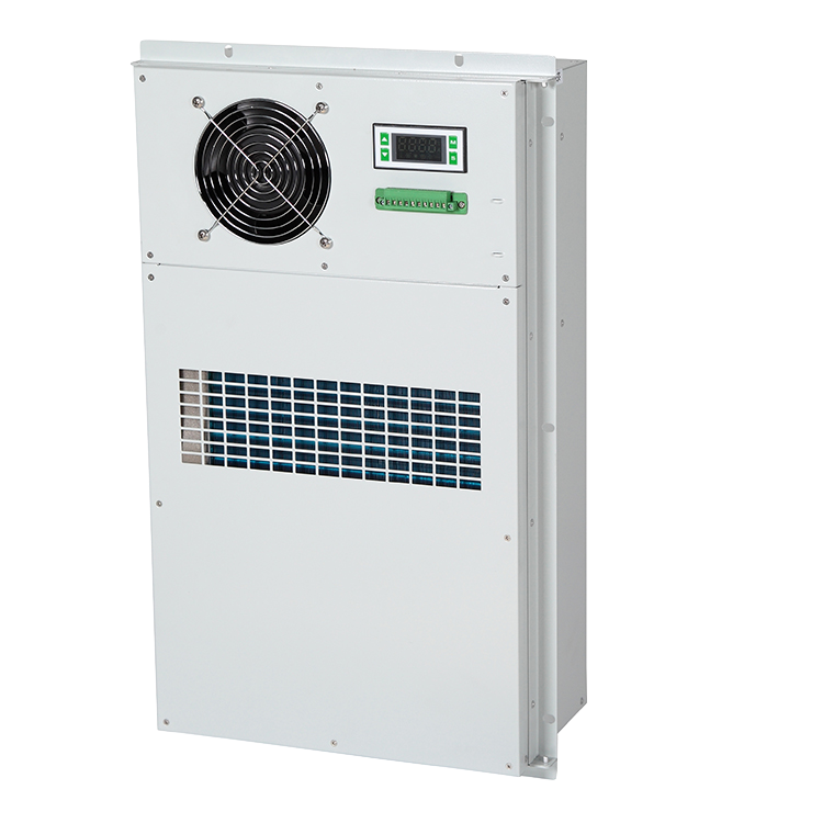
The official TELECOOL page describes door-mounted DC cooling for telecom cabinets with variable-speed compression, EC fans, dry-contact alarms and RS485 monitoring. Its linked four-page E1803V01.5 brochure has a wider and different scope: AC air conditioners, −48 VDC air conditioners and cabinet heat exchangers. Their table entries cannot be combined into one DC-only model family with one operating envelope.
The code distinguishes ACA air-conditioning units from ACE heat-exchange units, and uses 100 W units for air-conditioning capacity versus 10 W/K for heat-exchange performance. The same number in those two codes does not mean the same cooling duty. This page brings the original constructions together so buyers can select the right method, supply and cabinet interface without relying on the landing page's general claims.
This is an equipment family; its range does not identify one orderable configuration.
Swipe the table, or focus it and use arrow keys, to read the conditions and sources.
| Parameter | Published value | Conditions and evidence |
|---|---|---|
| AC example: ACA010EA1 | 220 VAC ±15%, 50 Hz; 1,000 W cooling and 410 W consumption at L35/L35 | PDF page 2 AC table; not an outdoor-design-day selection or a DC version. Source |
| DC example: ACA010ED1 | −48 VDC; 1,000 W cooling and 280 W consumption at L35/L35 | PDF page 3 DC table; voltage operating tolerance and full curve not supplied. Source |
| Heat-exchanger example: ACE010ED1 | −48 VDC; 100 W/K; 129 W consumption; 850 m³/h airflow | PDF page 3 exchanger table. W/K is not watts of rated refrigeration capacity; the L35/L35 table label needs clarification. Source |
| Air-conditioning temperature rows | Working −15 to 55 °C; separate 'application' −40 to 70 °C | AC/DC sample tables; webpage instead prints outdoor operation −40 to 55 °C. Meaning/version must be resolved. Source |
| Air-conditioning construction | Embedded mounting; R134a; IP55 table entry | AC/DC brochure entries; installed-cabinet seal, cut-out and current conformity scope require separate confirmation. Source |
| Published control interface | Dry-contact alarms; AC section names RS485 Modbus RTU | Actual protocol/card on each chosen version and alarm/fail states remain to be specified. Source |
ACA air conditioners list cooling in W and name R134a. ACE heat exchangers list W/K and have their own supply, temperature and dimensional schedules. Do not select an ACE010ED1 as a 100 W air conditioner or compare its 100 W/K entry directly with a 1,000 W ACA unit. Ask for the heat-exchanger performance curve and the temperature-difference definition used in its selection.
The exchanger table puts L35/L35 beside the W/K rating without explaining the test/normalisation basis. This review leaves that issue visible rather than deriving guaranteed heat removal at an arbitrary temperature difference. The room/cabinet designer needs the actual internal load, ambient envelope and permitted cabinet temperature to decide which cooling method can satisfy the duty.
Example ACA010EA1: 220 VAC/50 Hz, 1,000 W cooling at the brochure's L35/L35 condition.
Example ACA010ED1: −48 VDC, 1,000 W cooling at L35/L35, with a different power and airflow schedule.
Example ACE010ED1: −48 VDC, 100 W/K performance entry; obtain its temperature-difference basis and curve.
The brochure code names A1 220/1/50, A2 220/1/60, A3 220/1/50&60 and D1 48 VDC. The DC table itself prints −48 VDC. A recommendation paragraph under the DC heading says 220 VAC, which conflicts with that table. Request the current exact supply diagram, polarity, permitted voltage range and nameplate rather than relying on the inconsistent paragraph.
The same nominal 1,000 W capacity has 410 W catalogue consumption on ACA010EA1 and 280 W on ACA010ED1. Those are source-condition entries for different versions, not a project-level energy result. Identify heater and other options, maximum current, starting behaviour and backup-power scope before comparing operating costs or battery endurance.
The website gives −40 to 55 °C outdoor operation. The AC and DC brochure tables separately label −40 to 70 °C 'application temperature' and −15 to 55 °C 'working temperature'. The heat-exchanger table has another working range, −40 to 65 °C. No explanation establishes that application temperature is continuous refrigeration operation, storage or another state.
Obtain the actual model's selected capacity and permitted continuous envelope at the cabinet load and ambient extremes. The brochure's T3 wording and the web page's broad claims are not an exact current test. Keep the selected construction and temperature definition together in the order.
The sample describes embedded mounting and gives dimensions both including and excluding flanges. For ACA010EA1 it shares 655 × 381 × 170 mm flange dimensions with ACA008EA1; the matching no-flange entry is 614 × 340 × 170 mm. The DC ACA010ED1 table uses 782 × 482 × 200 mm including flange and 745 × 445 × 200 mm without it. Those versions need different coordinated openings.
Request the actual cut-out drawing, door/support loads, fastening and sealing instructions and internal/external airflow clearances. IP55 is a supplier table entry, not evidence that the finished modified cabinet or every door seal has that protection. Keep the service/removal route and wiring accessible after the cabinet is populated.
The DC brochure lists a hydrogen-discharging option, while the exchanger section lists optional heating. Neither statement defines a complete battery-cabinet ventilation, temperature or safety design. Ask for the delivered option's drawings, capacity, controls and approved application and have the responsible cabinet designer close the system requirements.
The webpage's variable-speed and EC-fan descriptions are not tied to every ACA/ACE table model. Identify the selected compressor/fan/control version. Acoustic entries have no measurement distance or installed-cabinet conditions, so do not promise those noise levels at the user's site.
Obtain the current cabinet-unit selection, cooling or exchanger curve, electrical/polarity diagram, mounting drawing, option schedule, communications and alarm map. The AC feature section names Modbus RTU and NO/NC dry contacts; the current delivered DC or exchanger version still needs its own point list and fail-state description.
Factory acceptance should confirm the chosen supply, specified thermal condition, alarms and the agreed cabinet interface. The landing page claims ETL, but no current exact-model issuer listing was reviewed. The platform has not tested these units, verified site enclosure protection or measured field efficiency. Price, current availability, warranty and serial/conformity records need a supplier quotation and documents.
Compiled by HVACDeck Editorial. Source review identifies what the publication states; it is not an independent performance test or certification.
Editorial method and corrections · Report a detail with this page URL
Send the manufacturer your required duty, installation conditions and the unresolved items identified in this brief.
AIRSYS MOBILECOOL-OUTDOOR wall-mounted telecom cooling
AIRSYS DATACOOL-PACKAGE integrated room cooling
AIRSYS CYBERCOOL-MOD CW chilled-water room terminals
AIRSYS CYBERCOOL-MOD DXA air-cooled room cooling