
AIRSYS VENUS-ECS05 process-temperature chiller
A compressor-based semiconductor-tool temperature-control model whose linked table gives 10 to 60 °C, rather than the landing page's broad −80 to 80 °C wording.
From AIRSYS precision and process cooling
Individual product research · HVACDeck Editorial · Sources checked 2026-10-11

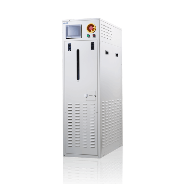
Resolve the ECS05 temperature range and fluid duty against the actual tool
VENUS-ECS05 is labelled the compressor-type constant-temperature liquid-cooling unit in AIRSYS's linked VENUS brochure. The model table specifies 10 to 60 °C, ±0.1 °C control accuracy and 10 kW cooling at a stated +20 °C point. It identifies FC-3283 as the heat-transfer fluid and R-404A as the refrigerant. Those are different circuits and substances.
The live VENUS landing page puts a broad −80 to +80 °C range and 1–20 kW capacity under ECS05. That does not agree with the linked model table. This brief uses the table's actual conditions as the documented example and makes the conflict visible. A buyer needs a current supplier-confirmed ECS05 selection, not a merged range assembled from the whole VENUS family.
Published parameters and their scope
The catalogue identifies a model reference; confirm the current revision and selected options.
- Model
- VENUS-ECS05
Swipe the table, or focus it and use arrow keys, to read the conditions and sources.
| Parameter | Published value | Conditions and evidence |
|---|---|---|
| Model table temperature / accuracy | 10 to +60 °C; ±0.1 °C | Original C1810V01.1 brochure model table; accuracy location and operating conditions require an acceptance definition. Source |
| Published cooling point | 10,000 W at +20 °C | Fluid-temperature condition as printed; ambient and full performance map not stated beside the table. Source |
| Named fluid and refrigerant | FC-3283 heat-transfer fluid; R-404A refrigerant | Separate table rows; current supply and tool/material compatibility require supplier/OEM confirmation. Source |
| Published flow / pressure | Maximum 25 L/min, 0.5 MPa at +20 °C | Original row; pump curve and whether maxima are simultaneous are not established. Source |
| Power and envelope | 200–220 VAC, 3-phase, 50/60 Hz; 8.2 kW input; 400 × 900 × 1,500 mm W×D×H | Brochure example, with 30 A breaker wording; final electrical protection and service space need the current installation documents. Source |
Selection and application review
Obtain one controlled revision before specifying low temperature
The ECS05 landing-page range reaches −80 °C; the model table starts at +10 °C. The family brochure separately contains a low-temperature CS10LT model. That difference matters to procurement: the page does not establish that the tabulated ECS05 can operate at the lower temperatures. Ask AIRSYS to identify the exact variant, corrected range and current revision, and to provide the selected capacity at every required setpoint.
Do not use a family marketing range to meet a tool's low-temperature requirement. Specify the actual required steady-state temperature, transition profile and ambient envelope. A quoted model substitution should include its own fluid, electrical and connection documents.
Define what ±0.1 °C is measuring
The ECS05 table prints ±0.1 °C control accuracy without stating the measurement location, load profile or time interval. The brochure shows high-reliability refrigeration parts and transient-power protection, but supplies no witnessed stability trace for this order. Agree where the temperature is measured and what excursion, recovery and repeatability are allowed.
Use the semiconductor-tool vendor's interface to define the load cycle and permitted inlet conditions. Request a test covering the proposed piping/volume and the relevant heating/cooling changes. The published accuracy should not be presented as wafer, chamber or process-result accuracy.
Keep the transfer-fluid loop separate from refrigeration
The ECS05 model table identifies FC-3283 in the circulating loop and R-404A in the compressor circuit. Approve the actual transfer fluid, materials, hoses, seals, connectors and fluid preparation against the tool requirements. Ask which fluid is delivered, who fills the tool loop and what maintenance or handling documents accompany it.
The 10 kW cooling point is at +20 °C; the 25 L/min / 0.5 MPa row also references +20 °C. Obtain the selected pump curve and pressure limits, including the allowed tool pressure and actual hose/manifold losses. The table does not prove that every listed maximum can be delivered together.
Account for heating, rejected heat and power
The table lists two 1.0 kW heaters and an 8.2 kW input entry. Cooling capacity, heater rating and unit input are different quantities. Obtain the electrical load schedule, mode-dependent input, starting/control behaviour and the applicable installation/protection instructions rather than treating the cooling capacity as electrical consumption.
The tabulated envelope is 400 mm wide, 900 mm deep and 1,500 mm high. No service-clearance or heat-rejection connection diagram is included in the reviewed model spread. Ask for the current general arrangement, access route, heat-rejection boundary and connection schedule before committing to a tool bay.
Close controls and factory acceptance with the tool integrator
The table lists Analog/Digital/Serial interfaces but not signal ranges, protocol, point map, fail state or interoperability with a particular process tool. Define enable, ready, fault, flow, temperature and interlock responsibilities using the current OEM requirements. Obtain the actual communications and wiring documents and include their operation in the factory test.
CE, S-Mark and Semi-S2 appear in the table as design-standard entries, not reviewed current issuer certificates. The brochure describes cooperation with Korea's FST and Chinese local manufacture, but it does not identify the manufacturing serial record for a purchase. Request the actual producing entity, model revision, conformity documents and signed thermal/hydraulic acceptance result. Pricing, availability and process qualification remain unconfirmed.
Sources and review scope
Compiled by HVACDeck Editorial. Source review identifies what the publication states; it is not an independent performance test or certification.
- Official VENUS landing pageChecked 2026-10-11 · ECS05 broad-range statement conflicts with linked model table; no combined range inferred.
- Original VENUS C1810V01.1 brochureChecked 2026-10-11 · All five pages read; PDF page 2 model table visually inspected and assigned to ECS05 on the right-hand spread.
Editorial method and corrections · Report a detail with this page URL
Turn the evidence into an enquiry
Send the manufacturer your required duty, installation conditions and the unresolved items identified in this brief.
Continue the selection
Other equipment from this manufacturer
AIRSYS MOBILECOOL-OUTDOOR wall-mounted telecom cooling
AIRSYS DATACOOL-PACKAGE integrated room cooling
AIRSYS CYBERCOOL-MOD CW chilled-water room terminals
AIRSYS CYBERCOOL-MOD DXA air-cooled room cooling