
Integrated row-level cooling
Catalogue example: horizontal supply, rack power up to 15 kW; select the actual refrigeration/water form and service interfaces.
 HVAC & REFRIGERATION
A modular data-centre package combining containment, row/room cooling, racks, power and monitoring; the actual cooling arrangement and availability need a coordinated design.
From AIRSYS precision and process cooling
Individual product research · HVACDeck Editorial · Sources checked 2026-10-11
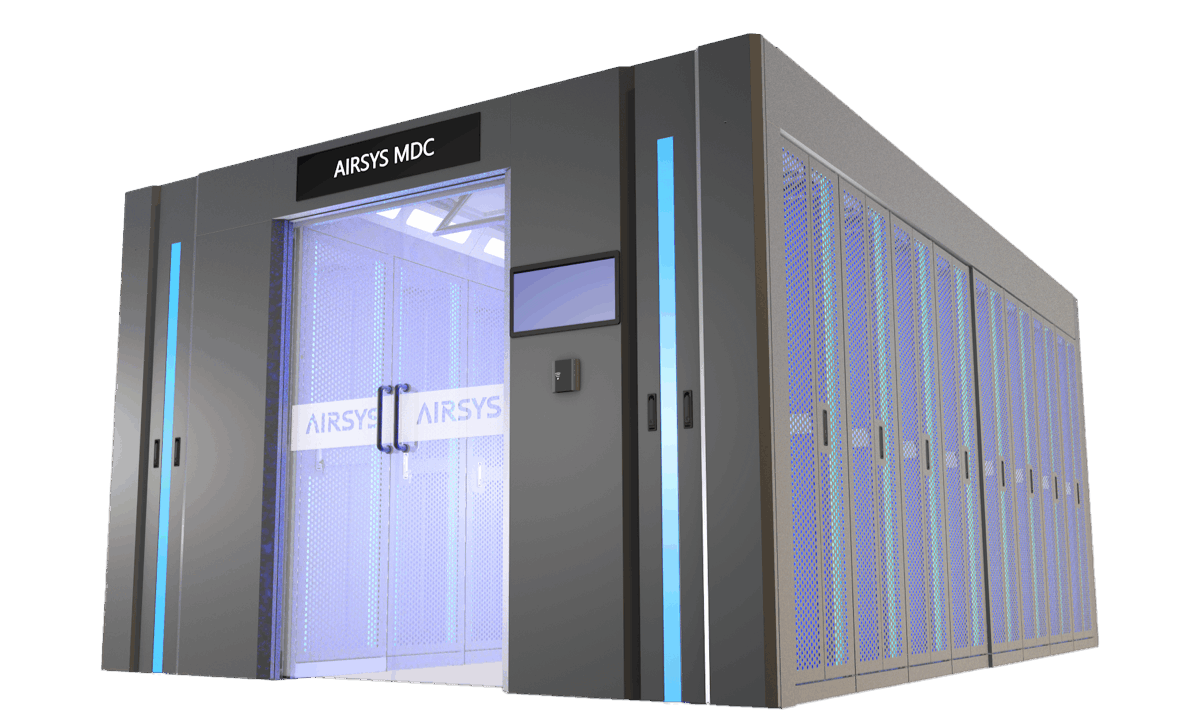
AIRSYS INNOVA Series MDC brings cooling, racks, UPS/distribution, cabling, monitoring and fire-related systems into a modular data-centre infrastructure package. The inspected webpage describes a double-row rack arrangement with hot/cold aisles. The linked 40-page Chinese infrastructure catalogue includes separate single-row and double-row sections, so its single-row capacity and dimensions should not be transferred into the double-row offer.
In the double-row section, pages 13–14 contrast built-in row-level cooling with external room-level cooling and different UPS/battery locations. The illustrative row-level arrangement lists rack power up to 15 kW; the room-level arrangement lists up to 5 kW. These are catalogue configuration limits, not demonstrated thermal capacities or a guarantee of site certification. Use a rack/load layout and complete dependency design to obtain one approved INNOVA configuration.
This is an equipment family; its range does not identify one orderable configuration.
Swipe the table, or focus it and use arrow keys, to read the conditions and sources.
| Parameter | Published value | Conditions and evidence |
|---|---|---|
| Integrated package | Cooling, racks, UPS/distribution, cabling, monitoring and fire-related systems | Official INNOVA portfolio; exact included equipment and engineering boundary require the quotation. Source |
| Double-row / row-cooling example | Up to 15 kW per IT rack; horizontal supply; air-cooled, water-cooled or chilled-water forms listed | Catalogue page 13 configuration, not one universal unit duty or verified installed rack temperature. Source |
| Double-row / external room-cooling example | Up to 5 kW per IT rack; downflow cooling | Catalogue page 14 arrangement; different air path and power-density scope from page 13. Source |
| Published illustrative rack | 2,000 H × 600 W × 1,200 D mm, 42U; 1,500 kg static load; 75% opening ratio | Double-row configuration schedule says dimensions may be customised; platform has not verified structural or thermal acceptance. Source |
| Monitoring expansion | Local collection and optional 3D/asset/capacity/temperature-map modules | Catalogue pages 37–38 distinguish base local software from expansion software; licence and actual integration not established. Source |
The double-row catalogue has one arrangement with row-level horizontal cooling and another with external room-level downflow. The corresponding rack power limits differ. Choose the actual air path and cooling medium before deciding where racks, containment, floor services and cooling equipment will sit. Do not simply apply a 15 kW/rack statement to the external room-level arrangement.
Request selected sensible capacity and airflow at the required return-air, ambient or water conditions. Define containment leakage, bypass, pressure and the permitted IT inlet temperatures with the hall designer. A rack's power limit is not the installed air condition or the available capacity after a cooling component fails.
Catalogue example: horizontal supply, rack power up to 15 kW; select the actual refrigeration/water form and service interfaces.
Catalogue example: downflow, rack power up to 5 kW; coordinate the room/floor supply and return path.
Separate catalogue section with its own dimensions and cooling figures; those entries are not copied into this double-row brief.
The webpage uses TIA-942 and Tier 3/4 wording, while the catalogue describes UPTIME tier configurations and domestic A/B/C classes. These are supplier design claims without a reviewed project certificate. Request the actual one-line and dependency diagrams, including cooling, power, controls and all common services. A supplier's tier label is not a current certification of the delivered room.
State the critical rack loads, growth profile, required maintenance state and allowed cooling/power failures. Establish remaining cooling and inlet temperatures with the agreed equipment or path out of service. Module scalability, UPS module redundancy and whole-site concurrent maintainability are different requirements.
Pages 13–14 show combinations with UPS/batteries inside, UPS inside with batteries outside, or both outside. Identify which arrangement is quoted and how its heat, access, cabling and support loads interact with the cooling/containment layout. The catalogue's 1,500 kg rack static-load entry is not the building-floor capacity or a dynamic handling rating.
Obtain a coordinated general arrangement for the actual rack widths, services and maintenance/removal routes. Define heat rejection, piping, drains, condensate, electrical feeds and the boundaries between factory-prepared modules and site works. Modular delivery does not remove the need to close those interfaces.
The web page describes remote management and optional expanded monitoring. The catalogue differentiates base local functions implemented in the MCS collector from expanded DCIM software that may be deployed on a physical/virtual machine or in a cloud platform. Obtain the included controller/software, licence, point map, communications and data-retention scope.
Select alarm routes, permissions, cybersecurity and ownership of remote access. The stated possibility of temperature maps, asset tracking or unattended operation is not evidence that every package includes the needed sensors/software or that it needs no site operator. Include the agreed monitoring and cooling-control interactions in functional acceptance.
The supplier markets PUE below 1.4 and rapid installation; the brochure also mentions a 21-day delivery scenario. No measured site data, confirmed stock or project programme was reviewed. Define the energy boundary, IT load, weather, power losses, cooling modes and redundancy state for an efficiency calculation. PUE for an infrastructure package is different from a single cooling unit's EER or cooling-system pPUE.
A useful handover includes the approved arrangement, included/excluded works, selected cooling schedules, one-lines, controls, current conformity evidence and witnessed failure/commissioning results. Obtain a dated programme and contract for delivery or performance commitments. This platform has not certified a site or tested an INNOVA installation.
Compiled by HVACDeck Editorial. Source review identifies what the publication states; it is not an independent performance test or certification.
Editorial method and corrections · Report a detail with this page URL
Send the manufacturer your required duty, installation conditions and the unresolved items identified in this brief.
AIRSYS MOBILECOOL-OUTDOOR wall-mounted telecom cooling
AIRSYS DATACOOL-PACKAGE integrated room cooling
AIRSYS CYBERCOOL-MOD CW chilled-water room terminals
AIRSYS CYBERCOOL-MOD DXA air-cooled room cooling