
What the picture establishes
An axial casing and top motor/transmission arrangement, not complete sealing or guard design.
Read the source HVAC & REFRIGERATION
Evaluate the external motor arrangement, stated gas-temperature boundary and correctly identified blade schedule together.
From Gaobeidian Gerui · General and process-air fan manufacture
Individual product research · HVACDeck Editorial · Sources checked 2026-10-11
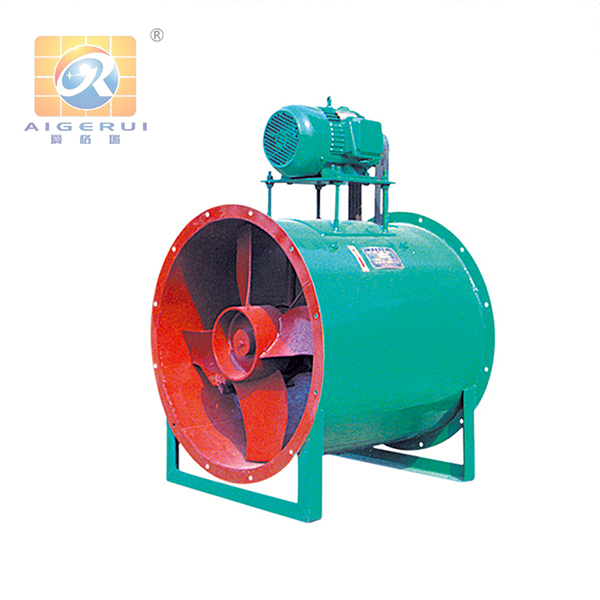
Gerui positions GD30K2 for humid or other gas streams that can adversely affect the motor, and describes installation between duct sections. The original family photograph shows a cylindrical axial casing with the motor mounted above it and a visible external transmission area. That construction question is materially different from selecting an ordinary axial casing by airflow alone. The photo does not establish belt/shaft sealing, corrosion-resistant materials or explosion-protection approval.
The official body limits gas temperature to 60°C and compares the family with FBZ-11/CZL-11 predecessors. Its actual table separates four- and six-blade schedules and includes speed, motor, flow and total pressure. Several size cells are genuinely blank in the original HTML; they are not merely lost during text extraction. This brief uses only clearly identified rows, keeps medium suitability conditional and requires the issued current construction and curve before procurement. It creates one family page, without multiplying blade counts or nominal sizes into separate URLs.
This is an equipment family; its range does not identify one orderable configuration.
Swipe the table, or focus it and use arrow keys, to read the conditions and sources.
| Parameter | Published value | Conditions and evidence |
|---|---|---|
| Supplier application | Humid or motor-adverse gas streams; duct intermediate installation | Broad application description, not universal chemical/hazardous-gas compatibility. Source |
| Published temperature boundary | Gas temperature must not exceed 60°C | Exact body limit; no special high-temperature or smoke-exhaust option verified. Source |
| Original pictured construction | Axial casing with motor above it and external transmission area | Photo inspected; seal details, exact transmission and ordered materials require issued drawings. Source |
| Four-blade No.10 example | 960 r/min; Y132M1-6 4 kW; 22600–29700 m³/h; total pressure 206 Pa | Clearly identified original table row; reference air/gas and complete curve absent. Source |
| Six-blade No.10 example | 960 r/min; Y132M1-6 4 kW; 24000–30000 m³/h; total pressure 226–255 Pa | Separate blade-count schedule; not a guaranteed adjustable conversion of the same delivered unit. Source |
| Source defects | Several actual size cells blank; motor typography inconsistent | Original table HTML checked; unidentified rows not assigned guessed sizes. Source |
The website's description of motor-adverse gas does not establish that every part of GD30K2 is suitable for any corrosive or combustible stream. Issue gas composition, humidity/condensation, temperature and contaminants. Ask the supplier to name the selected casing/impeller, shaft/drive arrangement, materials and required conformity scope.
The photo shows the motor outside the cylindrical casing, but does not expose how the shaft and connections are sealed. Request the actual section and interface drawing, leakage limits where relevant and maintenance instructions. A relocated motor is not, by itself, chemical compatibility, gas-tightness or explosion certification.
The four-blade No.10 row at 960 r/min lists a 4 kW Y132M1-6, 22600–29700 m³/h and 206 Pa total pressure. The six-blade No.10 row at the same listed motor/speed has 24000–30000 m³/h and 226–255 Pa. These are supplier schedule examples, with no reviewed common air-reference conditions or witnessed test.
Ask for the precise rotor/blade arrangement and selected curve. Do not describe the two blocks as a field-adjustable blade conversion. Several other size cells are empty in the actual source table, so their flow values cannot safely be mapped to an invented model size. Obtain a corrected schedule rather than inferring the missing entries by sequence.
The supplier proposes intermediate duct placement. Provide the connecting duct geometry, supports, connection flanges and the actual required pressure convention. The table says total pressure; it does not declare available external static pressure for an arbitrary duct arrangement. Require the selected curve and written rating basis at the intended gas conditions.
The top motor/transmission area needs the manufacturer's guarding and service clearances. Obtain alignment, tension or coupling instructions applicable to the actual drive, together with permitted motor/drive replacement access. No guessed belt specification or operational adjustment procedure is supplied by this directory.
Clarify motor supply, electrical input, speed-control compatibility, protection settings and the response to a drive or airflow fault. The motor kW table is not a measured package-consumption figure. Request selected sound and vibration data with their test basis rather than inferring low noise from the casing.
Approve a dated medium/material selection, current dimensional and drive drawings, corrected model schedule and agreed balance/run/performance checks. Current price, availability and independent compatibility or efficiency tests were not established. The source's predecessor-replacement statement is not proof of drop-in dimensional or electrical equivalence.
An axial casing and top motor/transmission arrangement, not complete sealing or guard design.
Read the sourceSpecified No.10 examples in distinct blade-count blocks, with total pressure and motor columns.
Read the sourceActual gas suitability, materials, current curve, transmission, protections and conformity scope.
Read the sourceCompiled by HVACDeck Editorial. Source review identifies what the publication states; it is not an independent performance test or certification.
Editorial method and corrections · Report a detail with this page URL
Send the manufacturer your required duty, installation conditions and the unresolved items identified in this brief.
Gerui G6-41 boiler air fans · Role and operating-point evidence
Gerui XQ air-slide process fans · Air duty and interface selection
Gerui 9-19 high-pressure centrifugal fans · Correct schedule and duty
Gerui 4-72 centrifugal fans · Duty, transmission and catalogue consistency
Gerui T35 axial fans · Operating point and total-pressure selection