
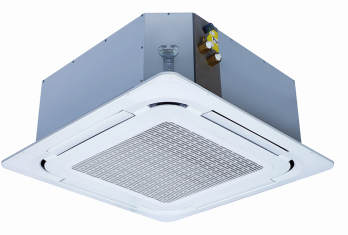
Yilaide FP-KM-2-D8 eight-outlet fan coils
Read the conditioned thermal schedule together with ceiling dimensions, pumped drainage and control options; resolve drawing/unit conflicts before fabrication.
From Yilaide Taizhou · Hydronic fan-coil manufacturing
Individual product research · HVACDeck Editorial · Sources checked 2026-10-11

Select the D8 hydronic cassette by speed, water duty and ceiling interfaces
Yilaide’s eight-outlet hydronic cassette is identified in its original documents as the FP-KM-2-D8 family, with rows from FP-34KM-2-D8 to FP-238KM-2-D8. The configuration sheet describes an ABS panel attached by four corner catches, copper-tube/hydrophilic-aluminium coil, washable synthetic filter, galvanised casing and condensate pump with level switch/check valve. It is a water-fed terminal: the published cooling/heating values do not describe an independent refrigeration plant.
For FP-85KM-2-D8, the high-speed row gives 850 m³/h and 4.50 kW cooling at 27°C dry bulb/19.5°C wet bulb entering air and 7/12°C water. Heating is 6.75 kW at 60°C inlet water and 4.50 kW at 45°C, with 21°C entering air and the same flow as cooling. This single family page keeps model rows and conditions together rather than creating thin URLs for each capacity.
Published parameters and their scope
This is an equipment family; its range does not identify one orderable configuration.
- Family designation
- FP-KM-2-D8
Swipe the table, or focus it and use arrow keys, to read the conditions and sources.
| Parameter | Published value | Conditions and evidence |
|---|---|---|
| Illustrative FP-85KM-2-D8 high-speed cooling | 850 m³/h; 4.50 kW | 27°C dry bulb/19.5°C wet bulb entering air; 7°C inlet/12°C outlet water. Manufacturer table, not a platform test. Source |
| FP-85 high-speed heating | 6.75 kW at 60°C inlet water; 4.50 kW at 45°C | 21°C entering air; flow stated the same as cooling. Separate rated conditions, not interchangeable outputs. Source |
| FP-85 hydraulic and electrical rows | 780 L/h; 30 kPa water resistance; 220 V / 1 phase / 50 Hz; 74 W, 0.34 A | Source hydraulic/electrical rows; power/current operating speed not explicitly repeated beside these entries. Source |
| Published noise entry for FP-85 | 43 dB(A) | No sound-power/pressure distinction, distance or detailed noise test arrangement in the inspected table. Source |
| Condensate configuration | Pump head stated 120 cm; level switch and check valve | Configuration image. Actual drain routing and permissible lift arrangement require installation instructions. Source |
| Dimension discrepancy for small D8 rows | FP-34/51/68 table body height 190 mm; drawing E = 200 mm | Original performance versus dimension image conflict. Larger FP-85/102/119 group has 290 mm in both. Source |
| Drain connection unit conflict | Technical row labels unit in and gives 26 | Cannot safely interpret as 26 inches or silently relabel as millimetres; obtain the current drawing/clarification. Source |


Selection and application review
Choose the operating speed at the actual room and water conditions
For FP-85, high/medium/low airflow is 850/638/425 m³/h and cooling is 4.50/3.60/2.70 kW at the listed cooling conditions. Select the terminal against the room load and the intended operating speed. A high-speed headline is not the same duty as quieter normal operation, and this source does not publish a separate sensible-capacity row to substitute for total cooling.
Heating values are tied to 60°C and 45°C inlet water with 21°C entering air. Require a current selection for a project using other supply temperatures, especially low-temperature heat-pump water. Do not extrapolate between temperatures or imply that the cassette produces hot/chilled water itself.
Coordinate the two-pipe terminal with the plant and valve package
The documented model suffix identifies the two-pipe D8 family. Close the actual plant changeover arrangement, valve/actuator scope, room control and coil water requirements. The source does not establish simultaneous independent heating and cooling connections for this unit; that is a different configuration to review.
The FP-85 row lists 780 L/h and 30 kPa water resistance. Ask for the pressure-drop basis and the selected valve and piping losses before sizing the pump or balancing the branch. The catalogue’s terminal energy-efficiency entries are not a whole chilled-water/heat-pump system COP, and the factory has not provided a current project-level efficiency guarantee here.
Approve the ceiling drawing and installation clearances
The FP-85/102/119 group has a 750 × 750 × 45 mm panel and a 660 × 660 × 290 mm body in the performance table. The dimensional drawing uses several lettered sizes for panel, body and mounting interfaces, so ask for the current drawing and ceiling opening rather than assuming the panel dimension is the cut-out.
The FP-34/51/68 body height is 190 mm in the performance table but 200 mm at drawing E. Larger-group plan dimensions also differ slightly between tables. Record these as unresolved revision questions and do not instruct installers to build around one silently chosen value. Reserve valve, pipe and removal access in addition to nominal body space.
Design pumped condensate drainage from an issued instruction
The configuration image states a 120 cm condensate-pump head and includes level protection and a check valve. That is not proof that every proposed lift, horizontal run and connection arrangement is permitted. Obtain the installation instructions, drain route and acceptable test procedure, then coordinate the overflow/fault signal with the terminal control.
The technical table’s drain outer-diameter row gives ‘26’ under an inches unit label. Its intended unit is unresolved; do not order pipe from a guessed conversion. Confirm the actual outlet fitting and routing. Agree insulation, access for cleaning and a condensate test for the installed arrangement.
Treat the eight-outlet panel as an air-distribution decision
The supplier describes eight discharge faces and an ABS panel with corner catches. Assess diffuser placement, obstacles, seating and draught/sound requirements with an issued air-distribution selection. The inspected material does not give throw, occupied-zone velocity or a validated room-temperature-uniformity result.
For FP-85, the table lists 43 dB(A), but without the detailed noise measurement basis. Request comparable sound data for the intended speed and installed ceiling arrangement. Low-noise marketing and the panel shape do not establish a room sound level or comfort guarantee.
Freeze controls and sample acceptance before an OEM order
The original configuration lists a main board/transformer, internal control with an external option, remote operation and optional wired control. Confirm what the quotation includes, supply protection, valve/control compatibility, communication functions and the permitted motor control. No EC motor or arbitrary building-management protocol is inferred from the cassette label.
Agree the current model/nameplate, panel, coil, drain and control documents plus sample thermal/hydraulic, electrical and condensate checks. The official page says actual parameters follow the unit nameplate; obtain that issued schedule before ordering. Price, lead time and independent installed performance remain unverified.
Select conditioned duty
Approve the required speed, room air and water temperatures/flow.
Close drawing conflicts
Confirm body/opening dimensions and the drain connection unit.
Test the approved sample
Check controls, valves, drainage and agreed thermal/electrical acceptance.
Sources and review scope
Compiled by HVACDeck Editorial. Source review identifies what the publication states; it is not an independent performance test or certification.
- Official eight-outlet family pageChecked 2026-10-11 · Complete page read; image-based tabs and manufacturer nameplate caveat inspected.
- Original D8 performance tableChecked 2026-10-11 · Full original table visually read, including model rows, cooling/heating test footnotes and problematic drain-unit entry.
- Original D8 dimensional drawingChecked 2026-10-11 · Full drawing and letter table inspected; small-model height mismatch and larger plan-dimension differences retained.
- Original standard configuration sheetChecked 2026-10-11 · Full materials/filter/drain/control sheet inspected; 120 cm pump statement distinguished from approved installation routing.
Editorial method and corrections · Report a detail with this page URL
Turn the evidence into an enquiry
Send the manufacturer your required duty, installation conditions and the unresolved items identified in this brief.
Other equipment from this manufacturer
Yilaide fan-driven chilled beams
Yilaide induction chilled beams
Yilaide FJ fan-assisted floor convectors
Yilaide natural-convection floor heating terminals