
Yilaide FJ fan-assisted floor convectors
Match a powered floor terminal to both the room load and the floor construction; one cooling-temperature heading remains unresolved.
From Yilaide Taizhou · Hydronic fan-coil manufacturing
Individual product research · HVACDeck Editorial · Sources checked 2026-10-11

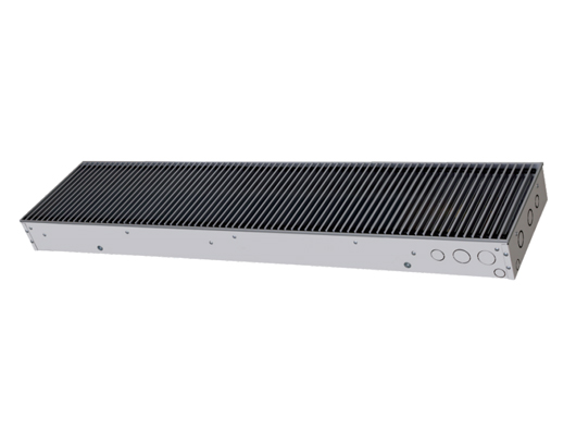
Coordinate FJ cooling, condensate and the floor pocket
Yilaide’s FJ floor convector uses forced air exchange and is described for both heating and cooling. Its floor-flush location differs from a ceiling fan coil: the pocket, removable grille, water circuit, electrical access and any condensate path must be designed as one installed assembly. The original schedule provides three cross-section groups and length-dependent air, thermal, electrical and weight entries.
The 95 × 280 × 1,250 mm reference lists 200 m³/h, 925 W heating at a 55/45°C water heading and 714 W cooling at 7/12°C. Room-air test conditions are not stated. A second cooling line is headed ‘16/45°C’, which is unclear and must not be silently rewritten. The reviewed drawing does not establish a complete drain arrangement or structural grille load rating; request those before committing a floor recess.
Published parameters and their scope
This is an equipment family; its range does not identify one orderable configuration.
- Family designation
- FJ
Swipe the table, or focus it and use arrow keys, to read the conditions and sources.
| Parameter | Published value | Conditions and evidence |
|---|---|---|
| Small FJ example | 95 × 280 × 1,250 mm; 200 m³/h | Original dimension and airflow group, not a project duct duty. Source |
| Conditioned water headings | 925 W heating at 55/45°C; 714 W cooling at 7/12°C | Original first-size row; entering room-air conditions not stated. Source |
| Ambiguous second cooling condition | Source heading 16/45°C; first-size output 328 W | No assumed correction to 16/19°C or any other return temperature. Source |
| Electrical/sound entries | 14 W input; 36 dB(A) | Smallest size reference; speed/electrical supply and sound test basis need issued data. Source |
| Hydraulic entries without unit | First size resistance: cooling 6; heating 5 | Image gives no resistance unit or water-flow value; do not assign kPa by assumption. Source |
| Range and weight | Cross-sections 95×280, 150×345, 200×400 mm; lengths 1,250/2,000/2,750 mm; first-size net weight 21 kg | Installed grille support/loading and total construction weight not established. Source |


Selection and application review
Select a cooling assembly with an explicit condensate strategy
The supplier describes both heating and cooling. Cooling at 7/12°C water can require a wet operation strategy depending on room conditions, but the reviewed source does not document the tray, drain outlet, pump or level protection. Request the actual intended dry/wet mode, condensate construction and permitted installation detail rather than assuming that any floor pocket may contain condensate.
Coordinate insulation and vapour control around water pipes and the pocket. Agree how leakage or drainage failure becomes visible and accessible. If the supplier proposes dry cooling, obtain the permitted water/dew-point control strategy and prove that the selected duty still satisfies the room requirement.
Resolve thermal and hydraulic conditions before comparison
Use the 55/45°C heating and 7/12°C cooling headings with their stated scope. Obtain the missing entering-air condition, selected fan operating point and water flow. The second cooling heading reads 16/45°C in the original image; retain it as a source question and request an issued correction or explanation.
The resistance row lists values without a unit. A buyer cannot complete a pump selection by treating 6 and 5 as kPa automatically. Require the unit, test flow and coil construction, then add the ordered valve and branch losses. This distinguishes a useful source reference from an approved building-services selection.
Make the recessed floor detail serviceable
The drawings show 95/150/200 mm depths, 280/345/400 mm widths and three length groups. Freeze the installed recess, finished-floor datum, grille supports, pipe/electrical routing and service openings using a current sectional drawing. The narrow body does not by itself reserve the space needed to remove the fan or heat exchanger.
Request the grille’s permissible loading and cleaning/removal instructions. The net-weight entry describes the machine, not the slab/support design. Coordinate access so routine dust removal and drain servicing can be done without dismantling adjacent permanent floor finishes.
Compare fan controls and noise at the same operating point
The small row lists 14 W and 36 dB(A); larger assemblies have different input and sound entries. The source does not specify the electrical supply, motor control or sound-measurement arrangement. Obtain the wiring/protection schedule and intended speed or modulation method. Do not label this an EC product merely because the input is modest.
Ask for comparable sound evidence at the selected airflow and installed grille arrangement. Grille free area, obstruction and floor-pocket construction affect the delivered result. A low catalogue number is not a guarantee of room noise or sufficient airflow after the builder’s finishes are installed.
Approve the full heating-and-cooling pocket
Issue both room loads, water conditions, permitted floor dimensions, selected sound requirement and the intended cooling mode. Request the exact FJ size, current thermal/electrical/hydraulic selection, drain package and approved floor section. Include valves and controls in a clear supply-responsibility list.
Close the ambiguous cooling heading and resistance unit before ordering. Acceptance should check fit, supports, controls, airflow, hydraulic balancing and drainage where applicable. Price, delivery and independent installed outcomes remain unverified; the brief prepares a complete enquiry rather than endorsing an incomplete schedule.
Close source questions
Confirm cooling heading, resistance unit and rating air conditions.
Approve cooling mode
Define dry/wet operation, insulation and drainage responsibilities.
Inspect the floor detail
Verify support, access, control and balancing requirements.
Sources and review scope
Compiled by HVACDeck Editorial. Source review identifies what the publication states; it is not an independent performance test or certification.
- Official family descriptionChecked 2026-10-11 · Complete description read; original product photograph visually inspected. Supplier comfort/noise claims not independently tested.
- Original dimensional drawingChecked 2026-10-11 · Full original drawing visually read; installed projections, support and maintenance clearances need current approved drawing.
- Original technical scheduleChecked 2026-10-11 · Full original schedule visually read. Missing or ambiguous conditions and units retained explicitly in this brief.
Editorial method and corrections · Report a detail with this page URL
Turn the evidence into an enquiry
Send the manufacturer your required duty, installation conditions and the unresolved items identified in this brief.
Continue the selection
Other equipment from this manufacturer
Yilaide fan-driven chilled beams
Yilaide induction chilled beams
Yilaide natural-convection floor heating terminals
Yilaide GFP-WAV-4 ducted terminal assemblies