
Yilaide WA concealed horizontal fan coils
Keep coil-row count, static-pressure option and model suffix together; the original tables contain both useful test conditions and unresolved entries.
From Yilaide Taizhou · Hydronic fan-coil manufacturing
Individual product research · HVACDeck Editorial · Sources checked 2026-10-11

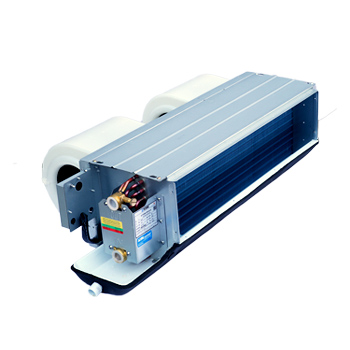
Select the WA ducted terminal without mixing its schedules
Yilaide’s concealed horizontal fan-coil page includes separate WA two-/three-row schedules and an additional WA-YC table. The original images distinguish coil configuration, outlet-static-pressure options and electrical/noise entries. One combined family brief keeps those differences visible; model capacity, coil-row count and pressure rows are not multiplied into thin pages.
For FP-85WA, the two-row high-speed entry is 860 m³/h and 4.01 kW cooling, while the three-row entry is 850 m³/h and 4.50 kW. The published cooling test condition is 27°C dry bulb/19.5°C wet bulb entering air and 7/12°C water. Heating uses 21°C entering air and 60°C or 45°C inlet water at the cooling flow. Confirm the exact coil and pressure configuration, because the same short model label does not settle all performance and installation options.
Published parameters and their scope
This is an equipment family; its range does not identify one orderable configuration.
- Family designation
- FP-WA / WA-YC
Swipe the table, or focus it and use arrow keys, to read the conditions and sources.
| Parameter | Published value | Conditions and evidence |
|---|---|---|
| FP-85WA two-row versus three-row cooling | Two-row: 860 m³/h, 4.01 kW; three-row: 850 m³/h, 4.50 kW high speed | 27°C dry bulb/19.5°C wet bulb air; 7/12°C water. Separate coil configurations, not a single merged row. Source |
| FP-85WA water duties | Two-row: 706 L/h, 27 kPa; three-row: 780 L/h, 30 kPa | Cooling-specific original rows; selected valve/branch losses additional. Source |
| FP-85WA two-row pressure options | 12/30/50 Pa outlet static: 74/86/97 W; 42/44.5/47 dB(A) | Source ties electrical/noise rows to outlet-static entries. Intended fan speed for those entries needs issued selection. Source |
| Sound evidence and anomaly | Page says sound pressure tested in a semi-anechoic room; FP-85 three-row image lists 43.5/37/32 dB(A) | Original values decrease across 12/30/50 Pa rows, unlike many adjacent entries. Retained as unconfirmed source data. Source |
| Mechanical reference for FP-85WA | Drawing: C length 925 mm, W 452 mm, H 232 mm; outlet 725 × 150 mm | Lettered drawing includes additional tray/connection positions; table height alone is not the service envelope. Source |
| Alternative WA-YC table | Same page provides a distinct suffix and different input/efficiency rows | Model/motor equivalence not established; never substitute its low input values into WA schedules. Source |


Selection and application review
Freeze coil rows and operating speed before comparing duty
The FP-85 two-row schedule has 860/645/430 m³/h and 4.01/3.21/2.41 kW cooling at high/medium/low speed. The three-row schedule has 850/638/425 m³/h and 4.50/3.60/2.70 kW. Identify the actual coil row and intended speed in the enquiry rather than requesting only ‘FP-85’.
Require a current selection at the room and water conditions. The stated 60°C and 45°C heating conditions are different outputs, not a guarantee at any hot-water supply temperature. No sensible-capacity split is provided in the reviewed image, so latent/sensible load fit needs additional supplier evidence.
Use the duct resistance and outlet-static option together
The page explicitly calls static pressure the unit’s outlet static pressure, and the schedules include 12, 30 and 50 Pa options. Provide the external duct/filter/damper resistance and the return/discharge arrangement. Ask for the selected operating airflow and pressure basis; do not treat a maximum airflow row and any pressure option as automatically compatible.
The electrical/noise entries change across those pressure rows. Obtain the actual selected fan/motor schedule and control method. Terminal efficiency entries are not a whole chilled-water plant COP, and the separate WA-YC input values are not substitutes for the ordinary WA configuration.
Close the sound and transcription questions
The page attributes sound-pressure testing to a semi-anechoic room under GB/T 19232-2019. A room sound level still depends on the installation and duct path. Request current comparable sound evidence for the chosen speed and pressure option.
The FP-85 three-row source lists 43.5, 37 and 32 dB(A) across its pressure rows; the pattern differs from neighbouring rows and the two-row schedule. Another heating entry also needs confirmation. Preserve the original file and obtain an issued correction/revision rather than silently repairing values or presenting these questionable entries as a quietness guarantee.
Approve the complete concealed assembly and maintenance access
Use the current dimensional drawing for mounting, coil connections, return box option and outlet transition. The original FP-85 drawing gives a 925 mm length, 452 mm width and 232 mm table height, but the drawing also shows tray/connection projections and different lettered dimensions. Confirm their datums and the installed service space.
The schedules distinguish weight with and without a return box. Close the actual supplied assembly, filter/access location, valves and drain connection. A narrow chassis dimension does not reserve enough space to remove the motor, coil or control components.
Accept the selected coil and pressure configuration
Issue the room load, required speed, water temperatures/flow, duct resistance, return arrangement, valve and control scope. Obtain the exact model/suffix, coil rows, current table and drawing revision with the quotation.
Agree thermal/hydraulic checks at stated conditions, electrical/noise evidence at the selected pressure option, and installed condensate/control checks. The manufacturer’s page says the unit nameplate governs actual parameters; obtain that current schedule before ordering. No price, stock, delivery or installed performance is verified here.
Select the actual configuration
Freeze suffix, coil rows, operating speed and outlet-static requirement.
Resolve source anomalies
Obtain current sound/heating entries and a signed drawing.
Approve the assembly
Agree return box, valves, drainage, controls and acceptance tests.
Sources and review scope
Compiled by HVACDeck Editorial. Source review identifies what the publication states; it is not an independent performance test or certification.
- Official concealed horizontal terminal pageChecked 2026-10-11 · Complete page including test-condition, sound-pressure and outlet-static-pressure statements read.
- Original WA two-/three-row scheduleChecked 2026-10-11 · Complete original two-row/three-row image and footnotes visually read. The FP-85 three-row sound entries and another heating entry require clarification.
- Original WA dimensional drawingChecked 2026-10-11 · Model-group dimensions and connection positions visually read; current selected assembly/datum drawing required.
- Separate WA-YC schedule on the same pageChecked 2026-10-11 · Complete alternative model-suffix schedule visually read. Values not mixed with WA coil-row schedules.
Editorial method and corrections · Report a detail with this page URL
Turn the evidence into an enquiry
Send the manufacturer your required duty, installation conditions and the unresolved items identified in this brief.
Continue the selection
Other equipment from this manufacturer
Yilaide fan-driven chilled beams
Yilaide induction chilled beams
Yilaide FJ fan-assisted floor convectors
Yilaide natural-convection floor heating terminals