
Yilaide fan-driven chilled beams
Separate dry/wet cooling and drainage from thermal speed selection; the source offers a pump but leaves controls and electrical duty undefined.
From Yilaide Taizhou · Hydronic fan-coil manufacturing
Individual product research · HVACDeck Editorial · Sources checked 2026-10-11

Select fan-beam water duty and the actual condensate package
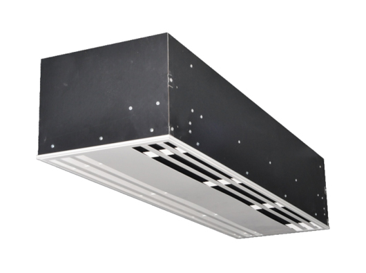
Yilaide’s fan-driven chilled beam is described for heating and cooling, including dry or wet cooling with an optional drain pump. Unlike its induction beam, this family uses forced air exchange inside the terminal. The official drawing and performance image provide useful size and speed references, but do not identify a complete model code, electrical schedule or the exact reference temperatures behind the duty-difference axes.
The high-speed row lists 345 m³/h with 355 W cooling at a 4 K difference and 1,085 W at 12 K. Heating is 1,750 W at 20 K and 5,400 W at 60 K. The drawing shows a 1,500 mm length, 595 mm face width and a 280 mm side height, with additional connection projections. Request the selected assembly and a defined dry/wet operating schedule rather than treating all these references as a fully specified room design.
Published parameters and their scope
This is an equipment family; its range does not identify one orderable configuration.
- Family designation
- Fan-driven beam
Swipe the table, or focus it and use arrow keys, to read the conditions and sources.
| Parameter | Published value | Conditions and evidence |
|---|---|---|
| Documented operation | Fan-assisted heating/cooling; dry or wet cooling; optional drain pump | Official description; exact supplied tray/pump and control package require confirmation. Source |
| Airflow by speed | 345/274/205 m³/h high/medium/low | Original schedule, without an external-static condition. Source |
| High-speed cooling | 355 W at 4 K difference; 1,085 W at 12 K | Original difference axis; reference air/water definitions not stated. Source |
| High-speed heating | 1,750 W at 20 K; 5,400 W at 60 K | Original schedule; cannot assume a particular inlet-water temperature. Source |
| Dimensional drawing | 1,500 mm length; face width 595 mm; side height 280 mm | Another view shows 603 mm across projections; not a single universal installation envelope. Source |
| Open selection data | No complete model code, water flow/resistance or electrical/sound table in reviewed image | No inferred motor type, pumping head or BMS protocol. Source |


Selection and application review
Choose dry or wet cooling as an installation decision
The source explicitly offers dry and wet cooling and an optional drain pump. State which mode is required for the project and obtain the complete tray, drain, insulation and controls for that mode. An optional pump is not an included accessory, and its head/flow or high-level protection was not supplied in the reviewed material.
For dry operation, request the allowable dew-point margin and control response at changing room humidity. For wet operation, approve the drain route and failure behaviour. Avoid transferring cassette pump heads or drain fittings to this beam; the exact pump assembly needs its own current specification.
Translate difference-based duty into an actual room selection
The cooling axis spans 4–12 K; the heating axis spans 20–60 K. Ask the supplier how each difference is defined and which air/water reference temperatures and flow apply. A 60 K heating difference is not proof of suitability for a 60°C inlet-water circuit.
The high/medium/low airflow rows are 345/274/205 m³/h, with different thermal outputs. Obtain the sensible/latent split and the selected speed under the intended cooling mode. The original image does not identify a model code or full coil selection, so use the values as traceable references while obtaining an issued duty sheet for the order.
Close fan electrics, controls and room sound
Request the motor type, electrical supply, input/current, protection and speed-control method. No such electrical schedule appears in the reviewed performance image. The three speed rows do not prove EC operation, a universal variable-speed signal or compatibility with a particular BMS.
Agree water-valve actuation, fan enable, humidity/dew-point response and any pump/high-level sequence. The description promotes low noise, but supplies no measured sound row here. Require comparable acoustic evidence for the intended speed and installed ceiling arrangement rather than promising a room noise level.
Use the full ceiling and connection drawing
The main drawing gives a 1,500 mm length, a 595 mm face width and a 280 mm side height; other views include a 603 mm dimension and several pipe/drain projections. Obtain the current ceiling opening, supports and clearances for the exact assembly. Do not flatten those different datums into one unqualified shipping or installation size.
Reserve valve, electrical, filter/fan and tray access. If a pump is ordered, confirm its location and replacement route. Define the ceiling-grid interface and how the terminal can be removed without damaging adjacent permanent finishes. The published drawing does not provide complete installed servicing instructions.
Approve a mode-specific fan-beam order
Provide the room loads, humidity limits, water plant conditions, intended fan speed, ceiling geometry and dry/wet mode. Obtain the exact model, conditioned thermal/hydraulic/electrical schedule and approved drain/control package. Include valves, sensors, pump and commissioning responsibilities in the quotation scope.
Acceptance should verify the installed fit, water balance, control operation and condensation/drain behaviour at agreed conditions, with acoustic checks where specified. This is a source-backed enquiry guide; no platform test, current price, stock position or independent room-performance result was established.
Select the cooling mode
Document dry/wet operation and the required condensate package.
Obtain a complete schedule
Define difference axes, actual water conditions and fan electrics.
Check installation functions
Agree controls, drainage, access and handover tests.
Sources and review scope
Compiled by HVACDeck Editorial. Source review identifies what the publication states; it is not an independent performance test or certification.
- Official family descriptionChecked 2026-10-11 · Complete description read; original product photograph visually inspected. Supplier comfort/noise claims not independently tested.
- Original dimensional drawingChecked 2026-10-11 · Full original drawing visually read; installed projections, support and maintenance clearances need current approved drawing.
- Original technical scheduleChecked 2026-10-11 · Full original schedule visually read. Missing or ambiguous conditions and units retained explicitly in this brief.
Editorial method and corrections · Report a detail with this page URL
Turn the evidence into an enquiry
Send the manufacturer your required duty, installation conditions and the unresolved items identified in this brief.
Continue the selection
Other equipment from this manufacturer
Yilaide induction chilled beams
Yilaide FJ fan-assisted floor convectors
Yilaide natural-convection floor heating terminals
Yilaide GFP-WAV-4 ducted terminal assemblies