
Yilaide GFP-WAV-4 ducted terminal assemblies
The high-static label needs an actual pressure/airflow selection; retain the original duty rows and wheel-material differences until the supplier closes them.
From Yilaide Taizhou · Hydronic fan-coil manufacturing
Individual product research · HVACDeck Editorial · Sources checked 2026-10-11

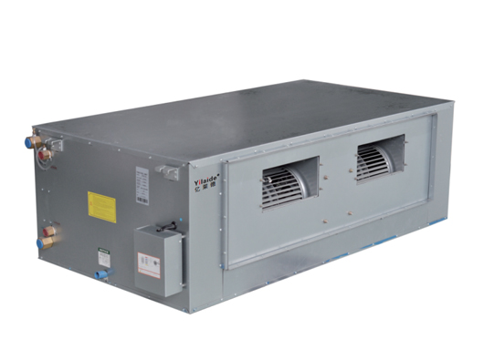
Select GFP-WAV-4 using a duct duty and current construction schedule
Yilaide lists GFP-WAV-4 as its high-static-pressure hydronic fan-coil family and supplies original configuration, performance and dimensional images. The source shows a larger ducted assembly with two forward-curved, double-inlet centrifugal wheels and optional thermostats and two-/three-way valves. No numerical outlet-static-pressure selection or fan curve is stated in the inspected performance image, so the category name alone cannot size a duct system.
The GFP-204WAV-4 high-speed row gives 2,053 m³/h, 12.6 kW cooling, 2,160 L/h water flow and 25.1 kPa water resistance; heating is listed as 18.8 kW. Air and water test temperatures are not supplied in that image. The description’s nominal airflow range differs from some actual table rows, and the configuration/performance sheets describe different wheel materials. Request a current issued selection and bill of construction for the ordered assembly.
Published parameters and their scope
This is an equipment family; its range does not identify one orderable configuration.
- Family designation
- GFP-WAV-4
Swipe the table, or focus it and use arrow keys, to read the conditions and sources.
| Parameter | Published value | Conditions and evidence |
|---|---|---|
| Actual GFP-204 high-speed entry | 2,053 m³/h; cooling 12.6 kW; heating 18.8 kW | Original table; thermal test temperatures and pressure duty not provided. Source |
| GFP-204 cooling water rows | 2,160 L/h; 25.1 kPa water resistance | Coil-side reference, excluding unprovided valve/branch losses. Source |
| GFP-204 electrical/sound rows | 220 V / 1 / 50; 564 W, 2.62 A; 55 dB(A) | Source values without detailed power-speed/sound measurement basis. Source |
| GFP-204 body reference | 1,290 × 568 × 390 mm; two fan wheels | Original performance/dimension group; installed access and projections require current drawing. Source |
| Wheel-material discrepancy | Configuration says aluminium-alloy wheel; performance says galvanised-steel forward-curved double-inlet wheels | The inspected sheets do not explain the difference. Actual ordered BOM must resolve it. Source |
| Missing duct-selection evidence | No numerical static-pressure condition or fan curve in the reviewed image | Do not borrow the ordinary WA family’s 12/30/50 Pa options or invent a high-static rating. Source |


Selection and application review
Turn a high-static label into an actual duct operating point
Issue the required delivered airflow and the pressure losses of the complete external system, including return/discharge ducts, filters and terminals. Ask for the selected fan curve and the consistent external-static or outlet-static basis. The inspected image gives airflow rows but does not identify their pressure condition.
The nominal family description says 1,360–5,100 m³/h, while the first GFP-136 row shows 1,001 m³/h at high speed. Use the issued selected-model schedule rather than equating model numbers or headline ranges with guaranteed flow. Neither another family’s pressure option nor maximum free airflow closes this selection.
Obtain the thermal conditions for the actual water plant
The GFP-204 row reports 12.6 kW cooling and 18.8 kW heating, but the image has no entering air/water temperature footnote. Require a current thermal schedule at the building’s supply/return water, room air and intended fan speed. Do not transfer the ordinary WA or D8 test conditions to this family by assumption.
Use the listed water flow and coil resistance as reference rows, then add the selected valve and branch losses. Establish water chemistry, pressure and coil materials for the order. The fan-coil assembly does not independently generate chilled/hot water or provide a refrigeration-plant COP.
Resolve wheel construction and controls in the order
The configuration sheet names an aluminium-alloy centrifugal wheel, while the performance table describes forward-curved galvanised-steel double-inlet wheels. Obtain the current bill of construction and confirm the selected motor/fan arrangement. No material superiority, corrosion tolerance or sound result is inferred from this unresolved mismatch.
The source offers three-speed operation and optional mechanical/electronic thermostats plus two-/three-way valves. Confirm the actual controls, electrical supply/protection, valve actuation and any BMS interface. A category label does not establish EC operation or a universal variable-speed control method.
Reserve space for a larger ducted assembly and service
The GFP-204 example is 1,290 × 568 × 390 mm in the original table and corresponding drawing group. Close the mounting points, coil connections, discharge/return openings, filter access and component-removal route with a current drawing. Larger models have their own size groups and cannot inherit this envelope.
The source describes a removable washable aluminium-alloy filter. Agree its installed location, pressure allowance and cleaning access. The 55 dB(A) table entry has no detailed sound test basis; obtain the data required to assess the actual duct/room sound requirement.
Accept the selected assembly at the duct duty
Prepare the enquiry with thermal conditions, water limits, complete duct resistance, airflow, room sound requirement, layout and valve/control scope. Obtain an issued model schedule, fan selection, drawing and BOM resolving the source conflicts.
Agree thermal/hydraulic and electrical tests plus performance evidence at the intended duct operating point, controls checks and condensate acceptance. Current stock, price, lead time and independent installed results are not established. The platform’s brief preserves actual source values and the questions necessary to make the purchase technically comparable.
Issue airflow and resistance
Provide the complete duct duty and require an actual pressure/flow selection.
Freeze construction and duty
Close thermal conditions, wheel material, fan/motor and valve/control scope.
Test the selected assembly
Agree measurable acceptance at the ordered operating conditions.
Sources and review scope
Compiled by HVACDeck Editorial. Source review identifies what the publication states; it is not an independent performance test or certification.
- Official Yilaide high-static fan-coil pageChecked 2026-10-11 · Complete page read; original product photograph and optional control wording inspected.
- Original performance tableChecked 2026-10-11 · Full original model table visually read. Test temperatures and detailed sound basis are not stated in this image.
- Original dimensionsChecked 2026-10-11 · Complete original drawing and model groups visually read; issued installation drawing still required.
- Original standard configurationChecked 2026-10-11 · Complete original construction, drain and motor/control entries visually read; optional items not assumed included.
- Original family descriptionChecked 2026-10-11 · Complete original family description visually read; supplier claims distinguished from witnessed tests.

Editorial method and corrections · Report a detail with this page URL
Turn the evidence into an enquiry
Send the manufacturer your required duty, installation conditions and the unresolved items identified in this brief.
Continue the selection
Other equipment from this manufacturer
Yilaide fan-driven chilled beams
Yilaide induction chilled beams
Yilaide FJ fan-assisted floor convectors
Yilaide natural-convection floor heating terminals