
Yilaide LM exposed hydronic fan coils
Choose a mounting and condensate orientation explicitly; the common chassis and optional feet do not remove the need for an issued installation drawing.
From Yilaide Taizhou · Hydronic fan-coil manufacturing
Individual product research · HVACDeck Editorial · Sources checked 2026-10-11

Coordinate LM mounting, return air and water duty
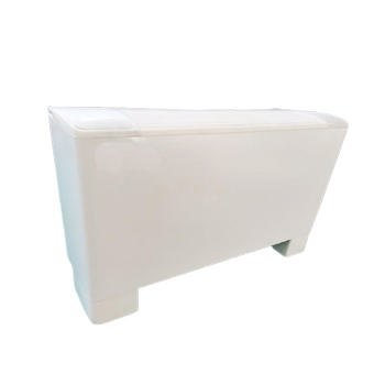
Yilaide’s exposed LM fan-coil family supports vertical, wall-mounted and suspended arrangements according to its embedded configuration sheet. The material describes a coated casing, selectable front/bottom return, common horizontal/vertical condensate trays and optional feet, valves and controls. A public product photograph shows a floor-standing appearance, but it does not approve every listed orientation for the pictured assembly.
The FP-85LM high-speed row is 850 m³/h with 4.50 kW cooling at 27°C dry bulb/19.5°C wet bulb entering air and 7/12°C water. Heating is 6.75 kW at 60°C water or 4.50 kW at 45°C, with 21°C entering air and flow stated the same as cooling. The original dimension images use orientation/foot-dependent values and an unclear drain-unit entry; get the ordered orientation’s current drawing rather than rotating a table dimension by guess.
Published parameters and their scope
This is an equipment family; its range does not identify one orderable configuration.
- Family designation
- FP-LM
Swipe the table, or focus it and use arrow keys, to read the conditions and sources.
| Parameter | Published value | Conditions and evidence |
|---|---|---|
| Published installation forms | Vertical, wall-mounted or suspended exposed terminal | Original embedded configuration; exact ordered orientation needs supplier approval. Source |
| FP-85LM conditioned duty | 850 m³/h and 4.50 kW cooling; 6.75/4.50 kW heating at 60/45°C inlet water | Cooling air 27°C dry bulb/19.5°C wet bulb, water 7/12°C; heating air 21°C, same water flow. Source |
| FP-85 water/electrical entries | 780 L/h; 30 kPa; 220 V / 1 / 50; 74 W, 0.34 A | Original rows, not a complete valve/branch duty or an arbitrary motor-control specification. Source |
| Optional feet and dimensional datums | Drawing shows 100 mm feet; table separates assemblies with/without feet | Performance table and drawing use different orientation-dependent dimension arrangements; do not assume one universal vertical height. Source |
| Return and service options | Front return; bottom return optional; washable synthetic filter | Original configuration; actual grille and service route need the selected drawing. Source |
| Unresolved drain unit | Performance table labels in and gives outer diameter 26 | No silently assumed millimetres. Request the actual outlet/fitting dimension. Source |
Selection and application review
Specify the exposed mounting arrangement first
Identify whether the unit stands vertically, hangs on a wall or is suspended horizontally. Obtain the approved installation assembly, fixings, tray orientation and connection drawing for that form. The supplier’s common-tray statement does not mean that installers may freely rotate a finished unit without following instructions.
The product photo is useful for the floor-standing appearance, not proof of all accessories or mounting approvals. Agree the enclosure finish, feet option and support loads with the actual order. Do not use one tabulated dimension as a universal vertical height for every orientation.
Design the visible terminal around return air and service access
The configuration offers front return with bottom return optional. Select the return arrangement against the proposed floor/wall/ceiling location, surrounding furniture and maintenance route. Obtain the discharge/return drawing and air-distribution data required for the room.
Reserve space for filter access, coil/valve service, electrical components and tray cleaning. The casing is described as removable coated metal, but no removal clearance or installed service time was established. A neat visible enclosure does not eliminate the need for water and drain access.
Select speed and water temperatures to meet the room load
FP-85 airflow is 850/638/425 m³/h and cooling is 4.50/3.60/2.70 kW at the source test conditions. Heating at 60°C inlet water differs from heating at 45°C; request a current selection for the actual plant, especially lower-temperature heat-pump supplies. No sensible/latent split or throw data is supplied here.
The table’s efficiency row concerns the terminal and is not a complete plant COP. The 43 dB(A) entry has no detailed measurement basis in this embedded image; require comparable sound data for the intended speed and installation rather than a room-noise guarantee.
Close condensate, dimensions and valves together
The original images distinguish with/without-feet dimensions and show a separate lettered drawing. Confirm which datums are body, mounting and total installed sizes for the chosen orientation. The stated 100 mm feet option changes the floor-standing arrangement; it is not a substitute for the full drawing.
The drain outer-diameter row gives 26 under an inches label. Obtain the current fitting specification and drainage instructions rather than making a guessed conversion. Select the optional two-/three-way valve and control arrangement, and confirm the route, insulation and access needed at the exposed location.
Agree an orientation-specific approval sample
An enquiry should include the room load, supply/return-water conditions, operating speed, mounting/return form, visible finish and valve/control/drain scope. Request the exact current model and drawing, resolving the source-unit/datum questions.
Agree thermal/hydraulic, electrical, control and condensate checks for the ordered orientation. Confirm service access, spare parts and actual contract terms. Neither price, delivery nor independently measured installed comfort has been verified by the platform; this is a source-based selection brief, not a completed room design.
Approve mounting and return
Freeze vertical/wall/suspended form, feet and front/bottom return.
Resolve installation datums
Obtain the current complete drawing and drain-fitting unit.
Test the ordered orientation
Agree duty, controls, condensate and service-access acceptance.
Sources and review scope
Compiled by HVACDeck Editorial. Source review identifies what the publication states; it is not an independent performance test or certification.
- Official exposed LM family pageChecked 2026-10-11 · Full page and all three embedded original images visually read; product photo inspected.
- Embedded original LM performance scheduleChecked 2026-10-11 · Full embedded performance image read, including air/water test footnotes, with/without-feet dimension rows and unclear drain-unit label.
- Embedded original LM dimension drawingChecked 2026-10-11 · Full lettered drawing and optional 100 mm feet entry read; installed orientation/datum must be confirmed.
- Embedded original LM configurationChecked 2026-10-11 · Vertical/wall/suspended forms, front/bottom return, common trays and optional valves/controls read. Files retained byte-for-byte privately.
Editorial method and corrections · Report a detail with this page URL
Turn the evidence into an enquiry
Send the manufacturer your required duty, installation conditions and the unresolved items identified in this brief.
Continue the selection
Other equipment from this manufacturer
Yilaide fan-driven chilled beams
Yilaide induction chilled beams
Yilaide FJ fan-assisted floor convectors
Yilaide natural-convection floor heating terminals