11 published equipment referencesLatest source review 2026-10-11
01 / COMPANY
What this manufacturer offers
Yilaide Fan Coil (Taizhou) Co., Ltd. is the current same-name legal manufacturer matched to CRM and the official site logo/footer. The preserved registration source records establishment on 15 January 2021 and manufacturing scope including fans and refrigeration/air-conditioning equipment. Its official contact address at Building 1, Huifeng Technology Industrial Park, Fengjiang, Luqiao, Taizhou matches the source registration.
The website also describes a founder working in terminal-unit production from 2000 and a differently named business registered in November 2004. That is presented as business history, not the incorporation date of the 2021 legal entity. The reviewed catalogue includes actual hydronic fan-coil configurations with original construction, performance and dimensional tables, providing a better basis for an OEM enquiry than promotional capacity counters. The catalogue distinguishes two-pipe changeover terminals from four-pipe heating and cooling configurations, so hydraulic circuit, control and ceiling interfaces must be reviewed together.
Current matched manufacturer
亿莱德风机盘管(台州)有限公司; CRM establishment 15 January 2021Same-name current logo/footer; 2004 website history concerns a separately named earlier business, not this incorporation date. Source
Current contact and registration locality
Building 1, Huifeng Technology Industrial Park, Fengjiang, Luqiao, TaizhouOfficial address agrees with the preserved source; confirm the exact operating workshop and visit arrangements. Source
Actual hydronic catalogue
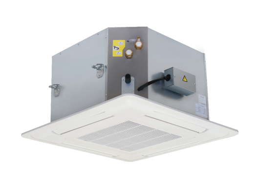
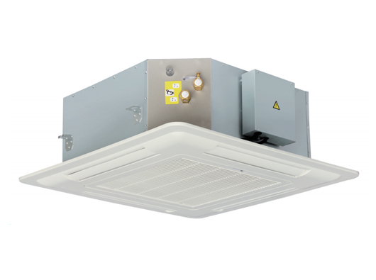
Two-/four-pipe cassettes, marine and self-draining configurations, directional air patternsReviewed official catalogue links; category names are not individually tested specifications. Source
Original eight-outlet evidence
FP-34KM-2-D8 through FP-238KM-2-D8 technical, construction and dimensional imagesFull original images visually inspected; document conflicts retained and no one-page-per-row expansion. Source
Relevant standard reference
GB/T 19232-2019 Fan coil unit; official portal marks it currentMetadata checked on national standard publication site. Full test clauses and current legal entity drafting status not verified. Source
Original manufacturing photographs
Coil stacks and sheet-metal cutting/forming equipmentFour supplier gallery images visually reviewed; no current equipment inventory, production rate or site audit inferred. Source
Swipe the table, or focus it and use arrow keys, to read conditions and sources.
Manufacturer-published information · FP-KM-2-D8
Parameter
Published value
Conditions and evidence
Illustrative FP-85KM-2-D8 high-speed cooling
850 m³/h; 4.50 kW
27°C dry bulb/19.5°C wet bulb entering air; 7°C inlet/12°C outlet water. Manufacturer table, not a platform test. Source
FP-85 high-speed heating
6.75 kW at 60°C inlet water; 4.50 kW at 45°C
21°C entering air; flow stated the same as cooling. Separate rated conditions, not interchangeable outputs. Source
FP-85 hydraulic and electrical rows
780 L/h; 30 kPa water resistance; 220 V / 1 phase / 50 Hz; 74 W, 0.34 A
Source hydraulic/electrical rows; power/current operating speed not explicitly repeated beside these entries. Source
Published noise entry for FP-85
43 dB(A)
No sound-power/pressure distinction, distance or detailed noise test arrangement in the inspected table. Source
Condensate configuration
Pump head stated 120 cm; level switch and check valve
Configuration image. Actual drain routing and permissible lift arrangement require installation instructions. Source
Dimension discrepancy for small D8 rows
FP-34/51/68 table body height 190 mm; drawing E = 200 mm
Original performance versus dimension image conflict. Larger FP-85/102/119 group has 290 mm in both. Source
Drain connection unit conflict
Technical row labels unit in and gives 26
Cannot safely interpret as 26 inches or silently relabel as millimetres; obtain the current drawing/clarification. Source
03 / PROJECT REVIEW
Evaluate Yilaide using actual fan-coil documents and entity boundaries
Use the water circuit and installation form to shortlist the offer
The site lists two-pipe and four-pipe cassette configurations alongside marine, self-draining and several outlet arrangements. A two-pipe unit’s plant/changeover interface differs from a four-pipe terminal’s separate heating and cooling connections. Air-distribution patterns and enclosure/dimension options also matter to the ceiling and occupied space. Choose on the actual hydraulic, control and installation requirements rather than the number of decorative outlet labels.
The website also has heat-pump and multi-split categories. Those category links do not establish a reviewed current model or a demonstrated manufacturing scope for every outdoor system. This profile concentrates on the actual fan-coil catalogue and leaves additional equipment subject to separate source review.
Resolve the contracting entity and historical claims
The current CRM entity is dated 2021; the website’s company history names Taizhou Yilaide Air-Conditioning Equipment Co., Ltd. in 2004. Obtain a current business licence, contracting/export name and any legal or brand-continuity documents needed for the order. Do not merge years, capital or historical credentials of two names into one verified entity.
The official contact address corresponds with the preserved source registration. Nevertheless, confirm the current production address, factory-visit contact and inspection location explicitly. A matched registration is an identity check, not proof that every advertised process is being performed there today.
What the reviewed manufacturing photographs actually show
Four original gallery photographs show stacked finned coils and sheet-metal work on a Han’s laser machine, a Yawei press brake and Yangli equipment. These are concrete supplier-presented process images rather than an invented list of factory capabilities. They do not establish the capture date, current ownership, throughput or which legal entity operates each machine.
For an OEM order, use these images to request a current process map: which coils are made internally, how sheet metal is cut/formed, which fan/control/plastic parts are bought in and where the finished terminal is tested. Obtain the current equipment and inspection records relevant to the ordered unit. A photo of a process is not evidence of thermal performance or conformity.
Coil work
Stacks of finned coils are pictured; confirm coil fabrication, pressure/leak tests and traceability.
Review manufacturing and product conformity at the ordered scope
The company describes R&D, terminal-unit manufacturing, OEM cooperation, management-system certification and CRAA certification. It also offers a manufacturing/R&D photo gallery. None of those materials is an independent site audit or a reviewed calibration/production-capacity record. Request the actual coil, sheet-metal, assembly and test responsibilities, including bought-in fans, controls and plastics.
Obtain the current certificate holder, scope, models and issuer verification where certification is claimed. Patent counts, area and model counters remain supplier statements without independently checked scope here. They are not used as a guarantee of throughput, performance or conformity for a particular order.
Use original conditions and resolve source inconsistencies
The eight-outlet D8 table states cooling at 27°C dry bulb/19.5°C wet bulb and 7/12°C water, and heating at 21°C entering air with 60°C or 45°C inlet water. Those conditions belong with the capacities; they cannot be compared directly to another terminal tested on different water/air conditions. Require the correct speed and the current issued selection.
The small-model performance height differs from the dimensional drawing and another connection row has an unclear unit. Request a signed current drawing and clarification instead of silently correcting the website. The official portal confirms the GB/T 19232-2019 standard reference, but this review does not claim that every depicted unit was independently tested to it or that the present entity’s drafting role has been verified.
Turn OEM scope into an approval and acceptance file
For a cassette or custom terminal, freeze water connections, valves, panel, ceiling access, motor/control specification, drain arrangement and service clearances. Ask for the actual unit schedule, drawings and an approval sample, not only an OEM logo/panel offer. Agree the production inspection and thermal, hydraulic, electrical and condensate checks appropriate to the ordered configuration.
Close price, lead time, packing, consumables, spares and service responsibilities with the real contracting company. The official email is retained separately in private CRM for a later authorised claim process; no message has been sent. This platform-written profile organises source evidence and sourcing decisions and is not an on-site audit or a warranty of installed comfort.
Define the terminal schedule
Issue pipe circuit, thermal/airflow duty, sound requirement and installation form.
Approve mechanical and controls scope
Freeze drawings, water/drain interfaces, panel, motor and controls.
Accept the actual order
Agree sample, current documents, production checks and service obligations.
07 / TRANSPARENCY
Sources and review scope
Compiled by HVACDeck Editorial. Page review: 2026-10-11. Publications are attributed below; their statements are not independent measurements by this platform.
Official Yilaide company accountChecked 2026-10-11 · Full supplier history/manufacturing account read. Present entity separated from 2004 predecessor name; certificates and production counters not independently verified.
Official Yilaide contact pageChecked 2026-10-11 · Address and two official email entries read; selected website email retained privately.
Official fan-coil catalogueChecked 2026-10-11 · Actual model-family links reviewed; no automatic page creation for every model or outlet variant.
Official eight-outlet D8 documentsChecked 2026-10-11 · Original product image, dimensions, standard configuration and complete technical table visually read.
National standard publication metadataChecked 2026-10-11 · Full metadata read: GB/T 19232-2019 current, published 30 August 2019, effective 1 July 2020. Does not establish product certification or current entity drafting status.
Official manufacturing photo galleryChecked 2026-10-11 · Four original images individually viewed: coil stacks, Han’s laser cutting, Yawei press brake and Yangli sheet-working equipment. Capture date/location and current ownership not independently established.
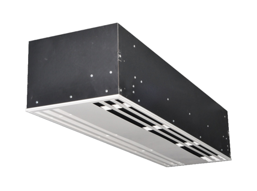
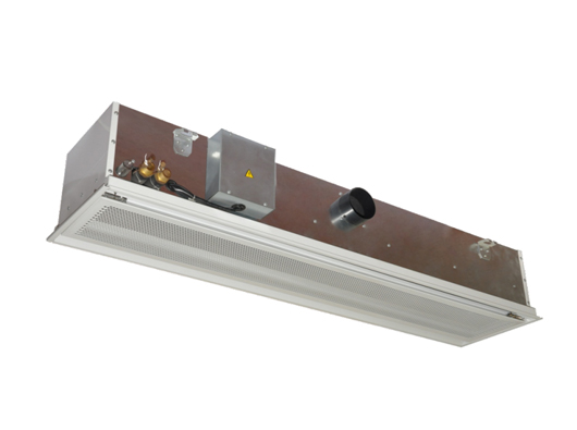
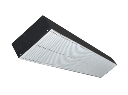
Official family descriptionChecked 2026-10-11 · Complete description read; original product photograph visually inspected. Supplier comfort/noise claims not independently tested.
Original dimensional drawingChecked 2026-10-11 · Full original drawing visually read; installed projections, support and maintenance clearances need current approved drawing.
Original technical scheduleChecked 2026-10-11 · Full original schedule visually read. Missing or ambiguous conditions and units retained explicitly in this brief.
Official family descriptionChecked 2026-10-11 · Complete description read; original product photograph visually inspected. Supplier comfort/noise claims not independently tested.
Original dimensional drawingChecked 2026-10-11 · Full original drawing visually read; installed projections, support and maintenance clearances need current approved drawing.
Original technical scheduleChecked 2026-10-11 · Full original schedule visually read. Missing or ambiguous conditions and units retained explicitly in this brief.
Official family descriptionChecked 2026-10-11 · Complete description read; original product photograph visually inspected. Supplier comfort/noise claims not independently tested.
Original dimensional drawingChecked 2026-10-11 · Full original drawing visually read; installed projections, support and maintenance clearances need current approved drawing.
Original technical scheduleChecked 2026-10-11 · Full original schedule visually read. Missing or ambiguous conditions and units retained explicitly in this brief.
Official family descriptionChecked 2026-10-11 · Complete description read; original product photograph visually inspected. Supplier comfort/noise claims not independently tested.
Original dimensional drawingChecked 2026-10-11 · Full original drawing visually read; installed projections, support and maintenance clearances need current approved drawing.
Original technical scheduleChecked 2026-10-11 · Full original schedule visually read. Missing or ambiguous conditions and units retained explicitly in this brief.
Original performance tableChecked 2026-10-11 · Full original model table visually read. Test temperatures and detailed sound basis are not stated in this image.
Original dimensionsChecked 2026-10-11 · Complete original drawing and model groups visually read; issued installation drawing still required.
Original standard configurationChecked 2026-10-11 · Complete original construction, drain and motor/control entries visually read; optional items not assumed included.
Original family descriptionChecked 2026-10-11 · Complete original family description visually read; supplier claims distinguished from witnessed tests.
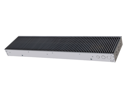
Official exposed LM family pageChecked 2026-10-11 · Full page and all three embedded original images visually read; product photo inspected.
Original WA two-/three-row scheduleChecked 2026-10-11 · Complete original two-row/three-row image and footnotes visually read. The FP-85 three-row sound entries and another heating entry require clarification.
Original WA dimensional drawingChecked 2026-10-11 · Model-group dimensions and connection positions visually read; current selected assembly/datum drawing required.
Separate WA-YC schedule on the same pageChecked 2026-10-11 · Complete alternative model-suffix schedule visually read. Values not mixed with WA coil-row schedules.
Original performance tableChecked 2026-10-11 · Full original model table visually read. Test temperatures and detailed sound basis are not stated in this image.
Original dimensionsChecked 2026-10-11 · Complete original drawing and model groups visually read; issued installation drawing still required.
Original standard configurationChecked 2026-10-11 · Complete original construction, drain and motor/control entries visually read; optional items not assumed included.
Original family descriptionChecked 2026-10-11 · Complete original family description visually read; supplier claims distinguished from witnessed tests.
Original performance tableChecked 2026-10-11 · Full original model table visually read. Test temperatures and detailed sound basis are not stated in this image.
Original dimensionsChecked 2026-10-11 · Complete original drawing and model groups visually read; issued installation drawing still required.
Original standard configurationChecked 2026-10-11 · Complete original construction, drain and motor/control entries visually read; optional items not assumed included.
Original family descriptionChecked 2026-10-11 · Complete original family description visually read; supplier claims distinguished from witnessed tests.
Original performance tableChecked 2026-10-11 · Full original model table visually read. Test temperatures and detailed sound basis are not stated in this image.
Original dimensionsChecked 2026-10-11 · Complete original drawing and model groups visually read; issued installation drawing still required.
Original standard configurationChecked 2026-10-11 · Complete original construction, drain and motor/control entries visually read; optional items not assumed included.
Original family descriptionChecked 2026-10-11 · Complete original family description visually read; supplier claims distinguished from witnessed tests.
Original D8 performance tableChecked 2026-10-11 · Full original table visually read, including model rows, cooling/heating test footnotes and problematic drain-unit entry.
Original D8 dimensional drawingChecked 2026-10-11 · Full drawing and letter table inspected; small-model height mismatch and larger plan-dimension differences retained.
Original standard configuration sheetChecked 2026-10-11 · Full materials/filter/drain/control sheet inspected; 120 cm pump statement distinguished from approved installation routing.