
Yilaide V/ACY shipboard hydronic cassettes
Evaluate condensate under vessel motion, marine approval scope and ship utilities before relying on the published terminal schedule.
From Yilaide Taizhou · Hydronic fan-coil manufacturing
Individual product research · HVACDeck Editorial · Sources checked 2026-10-11

Select the shipboard cassette against motion and utility conditions
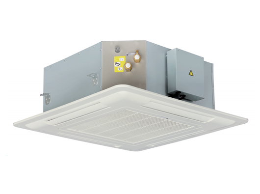
Yilaide markets its FP-KM4-V/ACY cassette family for shipboard hydronic terminal duty, with four air outlets and a condensate design that the supplier says limits leakage during significant vessel motion. The model table runs from FP-85KM4-V/ACY to FP-238KM4-V/ACY. Its original product photo and drawings show a ceiling cassette; no class-society approval, tested roll/pitch limit or marine type-approval file was available in the reviewed material.
The FP-85 row reports 850/640/430 m³/h at high/medium/low speed and 4.5/3.4/2.3 kW cooling. The same table gives high-speed heating of 7.0 kW, 780 L/h cooling-water flow and 16 kPa water resistance. It does not state the entering air/water test conditions, so these are published reference values that need confirmation, not a transferable shipboard design rating.
Published parameters and their scope
This is an equipment family; its range does not identify one orderable configuration.
- Family designation
- FP-KM4-V/ACY
Swipe the table, or focus it and use arrow keys, to read the conditions and sources.
| Parameter | Published value | Conditions and evidence |
|---|---|---|
| Documented family | FP-85KM4-V/ACY through FP-238KM4-V/ACY | Original model table and family description; KM4 is not evidence of four water pipes. Source |
| FP-85 cooling/airflow reference | 850/640/430 m³/h; 4.5/3.4/2.3 kW high/medium/low | No entering air/water temperatures stated in the inspected performance image. Source |
| FP-85 water/electrical rows | 780 L/h, 16 kPa; 220 V / 1 phase / 50 Hz; 86 W, 0.41 A | Water rows under cooling; electrical operating-speed basis not separately stated. Source |
| Condensate pump options | 70 cm head; 120 cm optional; level switch and check valve | Original configuration sheet, not an approved routing or roll/pitch test. Source |
| FP-85/102/136 assembly sizes | 705 × 705 × 290 mm body; 830 × 830 × 30 mm panel | Original table/drawing group; ceiling cut-out and service access need issued instructions. Source |
| Motion and certification evidence | Supplier states resistance to water leakage during vessel motion | No quantified roll/pitch/acceleration test or reviewed class approval provided. Source |


Selection and application review
Require a motion-specific condensate test
The family-description image says the terminal uses a special process so water does not leak or overflow during large vessel movement. That statement does not establish an angle, duration, acceleration, drain arrangement or witnessed test. Send the vessel designer’s operating motion envelope and request the applicable design/test evidence for the ordered unit.
Coordinate tray behaviour, pump performance, check valve and high-level protection under the actual installation orientation. Define the action on pump/level-sensor failure and the acceptable overflow response. The platform has not tested a moving vessel or established that a catalogue statement satisfies any class requirement.
Check the ship’s electrical and hydronic interfaces
The original table specifies 220 V, single phase, 50 Hz. Verify compatibility with the actual vessel distribution and protection requirements. A shore-based mains entry is not evidence of suitability for arbitrary marine voltages, frequencies, vibration or power-quality conditions.
Obtain the coil materials, corrosion exposure requirements, water chemistry and current pressure ratings. Agree the thermal schedule at the ship’s entering air and water temperatures, water flow and resistance. The inspected table has no test-temperature footnote, so the published cooling and heating numbers cannot be assigned another family’s conditions.
Close marine conformity and package scope separately
Request the applicable class/type-approval documents, their legal holder, exact models and limitations if approval is required by the project. Neither the ‘shipboard’ label nor the factory’s general certification claims establishes marine approval. Verify the ordered materials, electrical components and installation requirements within the actual scope.
The nominal family suffix is not proof of four-pipe heating/cooling circuits. Obtain the P&ID/connection schedule and control mode. Identify whether the panel, pump option, valves and any corrosion protection are included in the quotation rather than inferred from a promotional photo.
Approve ceiling service access and control options
For the FP-85 group, the table lists a 705 × 705 × 290 mm body and 830 × 830 × 30 mm panel. Use the issued drawing for mounting points, ceiling opening, water and drain connections. Allow access for coil, filter, pump and electrical service without assuming the panel size is the ceiling cut-out.
The page lists remote operation, optional wired control, optional master/slave control up to 32 units and an optional BMS function up to 2,048 units. Confirm the actual protocol, grouping, interfaces and supplied hardware. These maxima are not a commissioned network design, and no communication register list was reviewed.
Make a vessel-specific acceptance file
An enquiry should include the vessel/class requirements, motion environment, utilities, thermal duty, condensate route, enclosure/corrosion requirements and installation drawing. Obtain a current model/nameplate schedule and a clearly bounded quotation.
Agree thermal/hydraulic, electrical, condensate and relevant motion tests, with stated conditions and acceptance criteria. The FP-85 noise entry is 43 dB(A), but the image does not identify its detailed test basis; obtain comparable shipboard sound evidence. Current stock, price, delivery and independently proven operation remain unverified.
Issue the ship environment
Define motion, corrosion, class requirements and actual power/water utilities.
Approve the configuration
Close circuit, panel, drain pump, controls and service access.
Witness relevant acceptance
Agree test conditions and documents for the specific ordered marine unit.
Sources and review scope
Compiled by HVACDeck Editorial. Source review identifies what the publication states; it is not an independent performance test or certification.
- Official Yilaide shipboard cassette pageChecked 2026-10-11 · Complete page read; original product photograph and optional control wording inspected.
- Original performance tableChecked 2026-10-11 · Full original model table visually read. Test temperatures and detailed sound basis are not stated in this image.
- Original dimensionsChecked 2026-10-11 · Complete original drawing and model groups visually read; issued installation drawing still required.
- Original standard configurationChecked 2026-10-11 · Complete original construction, drain and motor/control entries visually read; optional items not assumed included.
- Original family descriptionChecked 2026-10-11 · Complete original family description visually read; supplier claims distinguished from witnessed tests.
Editorial method and corrections · Report a detail with this page URL
Turn the evidence into an enquiry
Send the manufacturer your required duty, installation conditions and the unresolved items identified in this brief.
Continue the selection
Other equipment from this manufacturer
Yilaide fan-driven chilled beams
Yilaide induction chilled beams
Yilaide FJ fan-assisted floor convectors
Yilaide natural-convection floor heating terminals