
Yilaide induction chilled beams
An active primary-air induction terminal with no internal fan; the nozzle/air/water selection and condensation limits remain system responsibilities.
From Yilaide Taizhou · Hydronic fan-coil manufacturing
Individual product research · HVACDeck Editorial · Sources checked 2026-10-11

Select induction nozzles with primary air and water together
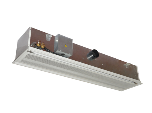
Yilaide’s induction chilled beam uses primary fresh or conditioned air through nozzles to entrain room air across its heat exchanger. The official description explicitly states that the terminal has no internal fan. It nevertheless depends on the central primary-air system, so the absence of a local fan does not remove upstream fan power, ventilation selection or acoustic design.
The original schedule separates beam length, small/medium/large nozzle groups, primary airflow and two temperature-difference axes. A 1,200 mm small-nozzle row at 40 m³/h lists 149 under both 4-degree difference columns and 30 dB(A). The numerical body has no clearly printed capacity unit, and its difference definitions need confirmation. Treat the schedule as selection evidence to resolve with the supplier, not a universal kW rating or a substitute for a coordinated primary-air and water design.
Published parameters and their scope
This is an equipment family; its range does not identify one orderable configuration.
- Family designation
- Induction beam
Swipe the table, or focus it and use arrow keys, to read the conditions and sources.
| Parameter | Published value | Conditions and evidence |
|---|---|---|
| Induction principle | Primary air through nozzles induces room air across the exchanger; no internal fan | Official family description; upstream ventilation/fan requirement remains. Source |
| Beam length group | 1,200/1,500/1,800/2,100 mm; 295 mm width and 250 mm height | Original schedule/drawing; air/water projections and ceiling cut-out need order drawing. Source |
| Small-nozzle 1,200 mm example | 40 m³/h primary-air row; 30 dB(A); table value 149 at both 4-degree columns | Capacity unit and temperature-difference definitions not clearly supplied in the original table. Source |
| Nozzle alternatives | Small/medium/large groups with separate airflow/noise rows | Not three independent product URLs or interchangeable operating points. Source |
| Drawing air connection | 100 mm nominal circle on original side drawing; B=A−400 mm | Connection datum and pressure requirement need issued selection. Source |
| Unprovided system data | No nozzle pressure, induction ratio, water flow/resistance or complete condensation control schedule reviewed | Cannot derive a complete ventilation or hydronic system from the published table. Source |


Selection and application review
Build the primary-air selection before relying on induction
Send the ventilation flow, primary-air temperature/humidity, available pressure and operating schedule. Ask for a nozzle selection that meets those conditions and the room’s exchange duty. The table’s air quantity belongs to a particular nozzle row; it is not evidence that all induced room airflow equals that number.
Obtain the nozzle pressure, induced-air ratio and discharge/throw data for the selected configuration. The reviewed source does not provide them. Check how turndown, occupancy changes and upstream control affect induction, thermal duty and ventilation. A fanless local terminal still needs a functioning primary-air system.
Use both temperature-difference axes with defined units
The original table groups primary-air temperature differences of 4/6/8/10 and water-temperature differences of 4/6/8/10. Require the reference room condition and the exact definition of each difference, including which water temperature is used. The table body does not clearly label its capacity unit, so do not convert its values into an asserted kW duty.
The 1,200 mm small-nozzle example at 40 m³/h has a numerical entry of 149 at the first intersection; other intersections change with both axes. Obtain an issued combined air/water selection and clarify whether the table includes both contributions. This avoids comparing a water-coil duty with a total terminal duty.
Define humidity control and condensation protection
Request the allowed operating water temperatures and the supplier’s intended dry-cooling limit, along with any dew-point sensing and valve interlocks. The reviewed page does not show a drainage or wet-cooling construction for this induction family. Do not borrow the fan-beam family’s optional pump or wet-operation statement.
Agree who removes the latent load and maintains room humidity through the primary-air plant. Evaluate startup, open windows and humidity excursions against the actual project. Any proposed condensation safeguard requires a documented control response and commissioning check rather than an assumption based on the product name.
Coordinate ceiling fit and comparable sound evidence
The drawing gives 295 mm width and 250 mm height and shows a primary-air connection and a T-keel relationship. Obtain the selected length’s ceiling opening, supports, connection/service projections and water-valve access. Verify compatibility with the actual ceiling grid and maintenance route.
Sound rows vary by nozzle and airflow. The 30 dB(A) small-nozzle example has no detailed test arrangement in the reviewed image. Request a comparable measurement basis and installation guidance. Do not replace the source table with a general ‘silent’ claim merely because the terminal has no local fan.
Approve a coordinated beam and primary-air package
Prepare room sensible/latent loads, primary-air conditions, available pressure, water temperatures and ceiling constraints. Obtain the exact nozzle and length selection, defined output units, hydraulic data and a complete control/interface schedule. Identify the primary-air plant and water-system responsibilities separately from the beam supply.
Accept the installed system against agreed ventilation, thermal, humidity-control, balancing and acoustic requirements. Require access and maintenance instructions. No independent room-comfort test, complete system efficiency, delivery date or stock level was verified by this platform-written review.
Define primary air
Freeze ventilation, humidity, temperature and available pressure.
Close table definitions
Confirm capacity units and both temperature-difference axes.
Commission the combined system
Test air/water balance, controls and condensation safeguards.
Sources and review scope
Compiled by HVACDeck Editorial. Source review identifies what the publication states; it is not an independent performance test or certification.
- Official family descriptionChecked 2026-10-11 · Complete description read; original product photograph visually inspected. Supplier comfort/noise claims not independently tested.
- Original dimensional drawingChecked 2026-10-11 · Full original drawing visually read; installed projections, support and maintenance clearances need current approved drawing.
- Original technical scheduleChecked 2026-10-11 · Full original schedule visually read. Missing or ambiguous conditions and units retained explicitly in this brief.
Editorial method and corrections · Report a detail with this page URL
Turn the evidence into an enquiry
Send the manufacturer your required duty, installation conditions and the unresolved items identified in this brief.
Continue the selection
Other equipment from this manufacturer
Yilaide fan-driven chilled beams
Yilaide FJ fan-assisted floor convectors
Yilaide natural-convection floor heating terminals
Yilaide GFP-WAV-4 ducted terminal assemblies