
Yilaide VZ/A gravity-drain two-pipe cassettes
A pump-free condensate arrangement depends on an approved gravity route; resolve ceiling-height and model-drawing differences before selecting the terminal.
From Yilaide Taizhou · Hydronic fan-coil manufacturing
Individual product research · HVACDeck Editorial · Sources checked 2026-10-11

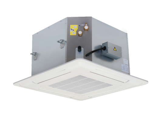
Assess VZ/A drainage geometry and two-pipe duty together
Yilaide’s FP-KM-VZ/A family is a two-pipe, four-outlet ceiling cassette designed with a special condensate tray and no drain pump, according to its original family-description image. This makes the gravity-drain route a primary selection constraint rather than a minor accessory decision. The source lists models from FP-34KM-VZ/A to FP-289KM-VZ/A and provides actual performance, construction and dimensional images.
For FP-85KM-VZ/A, the table gives 850/640/430 m³/h, 4.5/4.2/3.0 kW cooling and 7.0/6.3/5.0 kW heating at high/medium/low speed. Cooling water is listed as 780 L/h with 16 kPa resistance. The image does not state the thermal test temperatures, and the body dimensions differ from parts of the drawing. Confirm an issued current selection and installation sheet before reserving ceiling space or routing the drain.
Published parameters and their scope
This is an equipment family; its range does not identify one orderable configuration.
- Family designation
- FP-KM-VZ/A
Swipe the table, or focus it and use arrow keys, to read the conditions and sources.
| Parameter | Published value | Conditions and evidence |
|---|---|---|
| Drain principle | Special condensate tray; no drain pump | Explicit original description, not a pump option borrowed from another cassette. Source |
| FP-85 three-speed reference | 850/640/430 m³/h; 4.5/4.2/3.0 kW cooling | Original table; entering air/water conditions not provided. Source |
| FP-85 hydraulic/electrical rows | 780 L/h, 16 kPa; 220 V / 1 phase / 50 Hz; 76 W, 0.33 A | Published cooling-water and electrical rows; current issued schedule needed. Source |
| Drain connection | 26 mm outside diameter in performance table | This family explicitly uses mm, unlike the unresolved D8 unit label; connection drawing still needs confirmation. Source |
| FP-85 drawing conflict | Performance body 710 × 710 × 395 mm; drawing group includes 705 mm and a 397 mm side height | Source documents do not share all dimensions; no silently chosen installation clearance. Source |
| Construction and fan | Copper/hydrophilic-aluminium coil; galvanised insulated body; centrifugal wheel and three-speed motor | Original standard configuration image; actual supplied model/materials to be approved. Source |


Selection and application review
Decide whether the ceiling permits gravity drainage
The defining source statement is that this family has no condensate pump. Send the proposed unit position, drain termination and entire route to the manufacturer and obtain the permitted slope, lift restrictions and installation instructions. Do not apply the 70 or 120 cm pumped-drain values from other Yilaide families to VZ/A.
Coordinate structural and ceiling obstructions before approving the unit. If the route needs a lift, an alternative package requires a separate documented design; the platform does not establish that adding an arbitrary external pump preserves the unit’s approved installation or service scope.
Resolve body dimensions before committing the ceiling
The FP-85 group is 710 × 710 × 395 mm in the performance schedule, while the dimension image groups those models with a 705 mm plan figure and a 397 mm side height. The small and largest groups also need model-specific drawing confirmation. Use an issued revision that identifies overall body, mounting and opening dimensions rather than reconciling the numbers by guess.
The panel is 830 × 830 × 30 mm for the FP-85 group. Its outside size does not define the ceiling opening or the valve/pipe/service envelope. Reserve access for the filter, tray, coil and electrical box as well as the approved gravity drain.
Select speed and water duty on a common condition basis
FP-85 cooling decreases from 4.5 kW at high speed to 4.2 and 3.0 kW at medium/low; heating entries are 7.0, 6.3 and 5.0 kW. The actual room and water test temperatures are absent in this inspected image. Require a current thermal selection for the project instead of assigning D8 test conditions to these numbers.
The source labels this family two-pipe. Confirm the plant changeover, valve/actuator and control scope, water quality and pressure limits. Include the selected valve and branch piping in hydraulic assessment; the catalogue coil resistance alone does not size the whole circuit.
Check drain maintenance and the room control package
The configuration describes a moulded high-density polystyrene condensate tray and washable synthetic filter. Obtain the cleaning/service instructions, access drawing and the agreed procedure for checking the tray and drain. ‘Self-draining’ does not mean maintenance-free or immune to blockage.
The page lists remote operation with wired, master/slave and BMS options. Confirm which hardware and interfaces are supplied. Request the actual control/valve wiring and any condensation or overflow response relevant to the specified design; no automatic overflow-protection function is inferred merely from the absence of a pump.
Approve a sample with its real drain route
Prepare an enquiry with load and operating speed, entering air/water conditions, ceiling drawing, proposed gravity-drain route and controls. Obtain the current nameplate/model schedule and resolve the dimensional conflicts before fabrication.
Agree condensate drainage and leak checks in the actual permitted arrangement, along with thermal/hydraulic and electrical acceptance. The FP-85 noise row gives 43 dB(A) without the detailed measurement basis; obtain the sound data needed for the room design. Price, stock, lead time and installed outcomes have not been independently verified.
Approve gravity geometry
Submit the complete route and obtain the actual installation requirements.
Freeze the drawing
Resolve plan/height differences and allow service/valve access.
Accept the installed arrangement
Agree drainage, duty and controls checks for the approved sample.
Sources and review scope
Compiled by HVACDeck Editorial. Source review identifies what the publication states; it is not an independent performance test or certification.
- Official Yilaide self-draining cassette pageChecked 2026-10-11 · Complete page read; original product photograph and optional control wording inspected.
- Original performance tableChecked 2026-10-11 · Full original model table visually read. Test temperatures and detailed sound basis are not stated in this image.
- Original dimensionsChecked 2026-10-11 · Complete original drawing and model groups visually read; issued installation drawing still required.
- Original standard configurationChecked 2026-10-11 · Complete original construction, drain and motor/control entries visually read; optional items not assumed included.
- Original family descriptionChecked 2026-10-11 · Complete original family description visually read; supplier claims distinguished from witnessed tests.
Editorial method and corrections · Report a detail with this page URL
Turn the evidence into an enquiry
Send the manufacturer your required duty, installation conditions and the unresolved items identified in this brief.
Continue the selection
Other equipment from this manufacturer
Yilaide fan-driven chilled beams
Yilaide induction chilled beams
Yilaide FJ fan-assisted floor convectors
Yilaide natural-convection floor heating terminals