
Yilaide P/C four-pipe hydronic cassettes
Separate cooling and heating branch duties, valves and controls; the table’s two hydraulic rows must stay with their own circuits.
From Yilaide Taizhou · Hydronic fan-coil manufacturing
Individual product research · HVACDeck Editorial · Sources checked 2026-10-11

Coordinate the P/C four-pipe terminal with both water systems
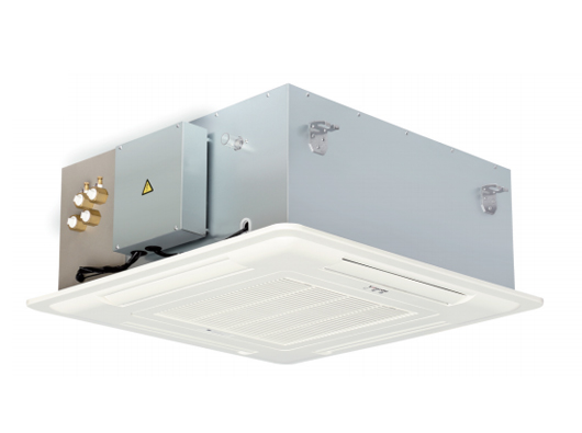
Yilaide identifies the FP-KM4-P/C family as a four-pipe, four-outlet hydronic ceiling cassette. Unlike a two-pipe changeover terminal, its original table gives separate cooling and heating water-flow/resistance rows and the drawing shows four water connections. Models range from FP-68KM4-P/C to FP-238KM4-P/C, with original construction and dimensional sheets available for review.
The FP-85KM4-P/C high-speed entries are 850 m³/h, 3.4 kW cooling and 4.5 kW heating. Cooling-water flow/resistance is 585 L/h and 18 kPa, while heating is 387 L/h and 1.5 kPa. The inspected image does not state the air/water test temperatures or establish simultaneous operating logic. Treat these as published circuit-specific reference rows and obtain a current issued selection, valve package and control sequence for the building’s actual chilled- and hot-water conditions.
Published parameters and their scope
This is an equipment family; its range does not identify one orderable configuration.
- Family designation
- FP-KM4-P/C
Swipe the table, or focus it and use arrow keys, to read the conditions and sources.
| Parameter | Published value | Conditions and evidence |
|---|---|---|
| Hydronic configuration | Four-pipe cassette; separate cooling and heating water rows | Official family description/table; drawing shows four water connections. Source |
| FP-85 high-speed thermal reference | 850 m³/h; cooling 3.4 kW; heating 4.5 kW | Entering air/water temperatures not stated in the inspected image; not a transferable project rating. Source |
| FP-85 cooling circuit | 585 L/h; 18 kPa water resistance | Cooling-specific row, not to be replaced with the heating values. Source |
| FP-85 heating circuit | 387 L/h; 1.5 kPa water resistance | Separate heating row; plant, valve and branch losses still require selection. Source |
| Motor and condensate options | Three-speed motor; five-speed optional; pump 70 cm head, 120 cm optional | Original configuration sheet; optional hardware not assumed included. Source |
| FP-85 size/electrical reference | 712 × 712 × 290 mm body; 830 × 830 × 30 mm panel; 220 V / 1 / 50; 76 W, 0.35 A | Original table and group drawing. Mounting dimensions and service envelope need current issued drawings. Source |


Selection and application review
Select the cooling and heating circuits independently
The FP-85 example has different cooling and heating water flows and resistances. Send the building’s actual chilled-water and hot-water supply/return conditions, room requirements and loads to the manufacturer. Require both issued thermal selections and avoid assigning one circuit’s water duty to the other.
The image does not state the test-temperature footnotes, so neither 3.4 kW cooling nor 4.5 kW heating can be transferred to arbitrary plant temperatures. Four pipes provide separate water interfaces; they do not, by themselves, establish the permitted simultaneous heating/cooling mode or an installed control strategy.
Close both valve packages and the room control sequence
Specify the cooling and heating valves/actuators, balancing and sensors, including what is supplied with the terminal. Obtain wiring, room-control logic and the agreed change between cooling, neutral and heating operation. A generic remote-control listing does not establish compatibility with any chosen plant/BMS.
The official page mentions optional wired control, master/slave control and BMS functions, but does not publish a current register map or commissioned network design. Agree actual hardware, protocol and failure behaviour. Prevent uncontrolled conflicting commands through a documented sequence approved by the responsible design parties.
Plan four water connections and pumped drainage in the ceiling
Use the original four-connection drawing and a current issued model drawing to approve pipe access, insulation, valves and supports. The FP-85 group has a 712 × 712 × 290 mm body and an 830 mm square panel in the performance table. Neither panel width nor nominal body height alone defines the ceiling opening and service envelope.
The configuration gives a 70 cm condensate-pump head with 120 cm optional, plus a level switch and check valve. Select the actual option and permitted drain route from installation instructions. Pump head is not a blanket allowance for any horizontal run or lift arrangement.
Compare airflow and sound at the intended operating speed
FP-85 airflow is 850/680/490 m³/h and cooling is 3.4/2.6/1.9 kW at high/medium/low speed. The heating entries are 4.5/3.4/2.4 kW. Choose an operating point that serves the room load and its air/sound requirement, with the missing thermal conditions closed by the supplier.
The table lists 43 dB(A) for this model but no detailed sound basis. Request comparable sound data for the selected speed and ceiling arrangement. The optional five-speed motor does not imply EC operation or an arbitrary variable-speed control method; obtain the actual motor and controller specification.
Accept the actual four-pipe package
The enquiry should identify both water systems, loads, operating speeds, valves, room/BMS controls, ceiling layout and condensate routing. Require the current model/nameplate schedule, drawings, component list and inspection/test plan.
Agree separate hydraulic/thermal checks for cooling and heating, valve/control sequence tests, electrical acceptance and condensate/level protection checks. Confirm service access and spare parts for the supplied pump, motor and controls. Current delivery, price and independently measured installed performance remain unverified; a four-pipe family label is not a completed project selection.
Issue both water duties
Define chilled/hot-water conditions and separate branch selection requirements.
Approve the interface package
Close four connections, valves, controls, pumped drain and service access.
Test the selected functions
Agree circuit, valve sequence, electrical and condensate acceptance.
Sources and review scope
Compiled by HVACDeck Editorial. Source review identifies what the publication states; it is not an independent performance test or certification.
- Official Yilaide four-pipe C-series cassette pageChecked 2026-10-11 · Complete page read; original product photograph and optional control wording inspected.
- Original performance tableChecked 2026-10-11 · Full original model table visually read. Test temperatures and detailed sound basis are not stated in this image.
- Original dimensionsChecked 2026-10-11 · Complete original drawing and model groups visually read; issued installation drawing still required.
- Original standard configurationChecked 2026-10-11 · Complete original construction, drain and motor/control entries visually read; optional items not assumed included.
- Original family descriptionChecked 2026-10-11 · Complete original family description visually read; supplier claims distinguished from witnessed tests.

Editorial method and corrections · Report a detail with this page URL
Turn the evidence into an enquiry
Send the manufacturer your required duty, installation conditions and the unresolved items identified in this brief.
Continue the selection
Other equipment from this manufacturer
Yilaide fan-driven chilled beams
Yilaide induction chilled beams
Yilaide FJ fan-assisted floor convectors
Yilaide natural-convection floor heating terminals