
Envicool prefabricated secondary loops · Distribution and site acceptance
Define branch flows, balancing, stainless materials and quick-connection tests before relying on rapid assembly claims.
From Shenzhen Envicool Technology Co., Ltd.
Individual product research · HVACDeck Editorial · Sources checked 2026-10-11

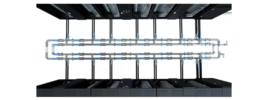
Specify the coolant distribution assembly around actual rack branches
Envicool's secondary-loop product is a prefabricated modular stainless-steel distribution loop for direct-to-chip liquid cooling. The public page describes quick chuck connections for site assembly without on-site cutting or welding and valve control of branch flow. Its original system illustration shows parallel distribution pipes connected to multiple rack-side branches. No pipe sizes, pressure class, valve schedule or rated flow distribution were published in the reviewed description.
This is a coolant-distribution assembly rather than a chiller or a rated heat-removal device. Its useful selection questions are the rack/branch load schedule, hydraulic balance, fluid cleanliness and demountable connection acceptance. The source's uniform-flow and high-reliability claims do not establish measured balancing tolerance or leak life. This brief requires actual drawings and commissioning criteria instead of treating the illustration's branch count as a fixed standard model or assigning a cooling capacity to the pipes.
Published parameters and their scope
This is an equipment family; its range does not identify one orderable configuration.
- Family designation
- Prefabricated secondary-loop family
Swipe the table, or focus it and use arrow keys, to read the conditions and sources.
| Parameter | Published value | Conditions and evidence |
|---|---|---|
| Assembly role | Modular secondary-side coolant distribution | Not a heat-generating or heat-rejection machine. Source |
| Material description | Stainless steel | No grade, tube dimensions or pressure class reviewed. Source |
| Connection approach | Quick chuck assembly; no site cutting/welding described | Actual joint/gasket specification and scope need issued drawings. Source |
| Branch control | Flow controlled through valves | No valve type, flow coefficient or balancing tolerance published. Source |
| Source illustration | Parallel distribution pipes with rack branches | Not a selected branch count or connection schedule. Source |
| Quantitative limits | No rated flow, pressure, size or cooling capacity issued | No numbers inferred from the drawing. Source |
Selection and application review
Translate rack heat loads into a branch schedule
Issue required coolant flow and temperature for each rack or load branch using the connected equipment's requirements. Include planned expansion and minimum/maximum load cases. Request a selected pipe and valve schedule with the hydraulic calculation and available pump boundary.
Uniform distribution is a supplier statement, not a measured flow tolerance. Agree target flows, measurement positions and balancing acceptance for the actual number of branches. The original illustration does not set a standard branch count.
Approve prefabrication and quick-joint interfaces
Obtain fabrication drawings, tolerances, support positions and the actual joint/gasket arrangement. Confirm rack/CDU connection type, pipe sizes and access for assembly, inspection and disconnection. No-site-welding language does not eliminate supports, alignment, seal inspection or pressure/leak testing.
Ask how thermal movement and mechanical loads are handled within the issued design. The word stainless does not supply a grade or rated pressure. Request material certificates and joint compatibility where required by the purchase specification.
Control clean delivery and filling
Agree cleaning, capping, shipping and storage procedures, then define flushing, filling and fluid-quality checks for the connected server system. Identify who supplies compatible coolant and who accepts the completed distribution loop.
Confirm whether valves, seals and all wetted materials match the actual fluid and temperature range. General reliability language does not establish protection against contamination or chemical incompatibility. No filtration or hygiene class is assumed from prefabrication.
Balance, isolate and expand the installed loop
Request the commissioning procedure and branch-flow measurement method. Agree how valves isolate a rack and what changes in other branches after isolation or expansion. Establish alarms/control responsibilities in the CDU or supervisory system rather than assuming the pipe assembly supplies them.
For future modules, approve capped connection points, drain/vent arrangements and any load/flow limits of the existing headers. Quick assembly does not prove expansion is possible without interruption or hydraulic reselection.
Accept the delivered distribution boundary
Inspect material/assembly records, support and joint installation, agreed pressure/leak test and measured branch balance. Obtain as-built drawings and a valve identification schedule for maintenance. Thermal duty belongs to the connected loads and heat-rejection equipment; no independent kW rating is assigned to this pipe family.
Current price, lead time, measured balancing tolerance and independent long-term joint reliability remain unknown.
Issue branch requirements
List rack flows, fluid limits and minimum/maximum-load cases.
Approve modular drawings
Freeze materials, quick joints, valves, supports and expansion scope.
Commission clean and balanced
Agree flushing, leak tests, measured branch flow and as-built records.
Sources and review scope
Compiled by HVACDeck Editorial. Source review identifies what the publication states; it is not an independent performance test or certification.
- Official secondary-loop distribution pageChecked 2026-10-11 · Complete assembly/valve description and original multiple-branch illustration read; no rated pressure/flow schedule available.
Editorial method and corrections · Report a detail with this page URL
Turn the evidence into an enquiry
Send the manufacturer your required duty, installation conditions and the unresolved items identified in this brief.
Other equipment from this manufacturer
Envicool MC power-container cooling · Heating, humidity and dry contacts
Envicool BattCool-AC container cooling · Air paths and standby control
Envicool BattCool-C / EMW chillers · Battery coolant and fault duty
Envicool EMA cabinet air conditioners · Air path and filter service
Envicool HC combo cabinet cooling · Heat-pipe and compressor modes
Envicool DC / EC outdoor cabinet cooling · Power and selected duty