
Envicool 4U liquid-to-liquid CDU · Circuit and rack interfaces
Read the 15/30/80 kW choices together and resolve the website’s secondary-loop wording with an issued P&ID.
From Shenzhen Envicool Technology Co., Ltd.
Individual product research · HVACDeck Editorial · Sources checked 2026-10-11

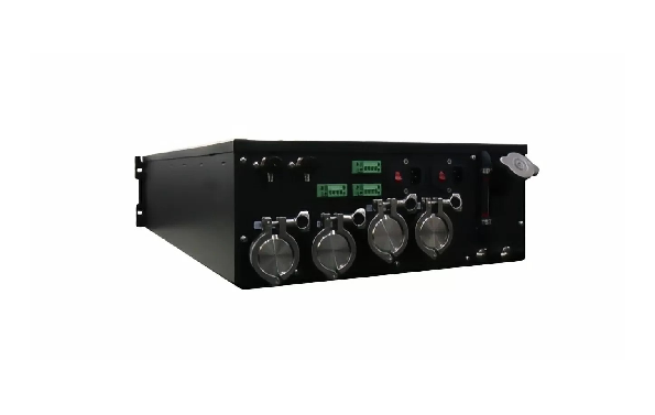
Select the rack CDU with both fluid interfaces explicitly documented
Envicool describes this in-rack liquid-to-liquid CDU as a 4U, 19-inch unit with a built-in plate heat exchanger. Its overview explicitly connects the primary loop to a chiller, dry cooler or cooling tower and the secondary loop to the load; an internal pump provides circulation. The page lists 15/30/80 kW capacity choices and 1+1 pump and power arrangements. The original rendering shows a rack-mount enclosure with several front connection assemblies, not a selected P&ID.
One feature says no secondary loop is needed, while the overview names a secondary loop. This brief preserves the discrepancy as a layout question instead of deleting a circuit from the selection. The capacity choices are kept on one family page because no separate model rating tables were reviewed. The more-than-10 dB(A) overall noise reduction is also a supplier comparison with no inspected baseline. A purchase needs actual primary/secondary temperatures, server-fluid requirements and rack interfaces, not an assumed water supply point or guaranteed sound result.
Published parameters and their scope
This is an equipment family; its range does not identify one orderable configuration.
- Family designation
- In-rack liquid-to-liquid CDU
Swipe the table, or focus it and use arrow keys, to read the conditions and sources.
| Parameter | Published value | Conditions and evidence |
|---|---|---|
| Rack format | 4U, 19-inch | Depth, weight and mechanical support not published in reviewed text. Source |
| Published capacity choices | 15 / 30 / 80 kW | No inspected individual-model or air/fluid rating table; one family page. Source |
| Overview circuit | Primary to heat sink; secondary to load; internal pump | Named external sinks include chiller, dry cooler and cooling tower. Source |
| Source inconsistency | Feature says no secondary loop; overview describes one | Resolve selected layout with supplier; do not infer missing hydraulic connections. Source |
| Resilience | 1+1 pumps and power supplies | Selected arrangement and remaining duty need confirmation. Source |
| Noise comparison | Overall noise reduced by >10 dB(A) | No inspected reference system or sound measurement basis. Source |
| Warm-water positioning | Close-coupled cooling using warm water | No numeric supply-temperature or dew-point limits issued. Source |
Selection and application review
Resolve the secondary-loop statement before a quote
Ask for the issued P&ID naming every facility-side and load-side connection, pump and exchanger circuit. The overview expressly describes a secondary loop, while a later feature says one is not needed. The latter may describe a reduced external routing requirement, but that interpretation is not verified and is not adopted here.
Specify who supplies manifold, server hoses, connections and heat-sink pipework. Agree the actual installation scope and fluid separation. A 4U enclosure does not remove the need to define a complete circulation path.
Select one capacity at the actual fluid conditions
Choose the required load and supply/return conditions, facility fluid and available flow/pressure. Request the selected 15, 30 or 80 kW model with exchanger approach, pressure losses and complete electrical input at those points. The source does not publish the conditions behind those capacities.
Confirm whether the facility sink is a chiller, dry cooler or cooling tower and obtain its available temperatures at the design climate. A list of compatible heat sinks does not make their ratings interchangeable or prove that a selected server temperature is always achieved.
Check rack support, connectors and fluid quality
Obtain depth, mass, rail/support drawings and front/rear service clearance. Verify the actual connection type, size and valve/isolation requirements on the selected model. The front connection rendering is not a specification for pressure rating, disconnect compatibility or safe operation.
Use server OEM limits to define coolant chemistry, materials, filtration, pressure and allowable temperature. Ask for filling, venting, flushing and sampling instructions. Warm-water language alone does not define safe chip temperatures or condensation limits.
Verify 1+1 arrangements across actual faults
Request one-pump and one-power-feed duty and the automatic transfer sequence. Confirm independent wiring and identify shared controls/exchanger parts that may limit continuity. Agree low-flow/high-temperature and leakage alarms and the connected server response.
Clarify which service interventions preserve cooling and which require isolation or reduced load. No full-duty uninterrupted-operation guarantee follows from a 1+1 label. Use the manufacturer's issued replacement and restart procedures.
Separate noise and energy comparisons from ordered performance
The stated overall noise reduction above 10 dB(A) refers to a comparison whose baseline and measurement positions were not inspected. Ask for selected sound data with operating condition and measurement basis; do not use the website number as an absolute sound level.
Acceptance should verify chosen thermal/hydraulic duty, complete input and agreed fault/control tests. Compare energy with the upstream heat sink included on a consistent boundary. Price, lead time and independently tested performance remain unknown.
Resolve the circuit
Approve primary/secondary P&ID and external scope before relying on simplified installation wording.
Select the duty
Choose one capacity at actual fluid, heat-sink and rack conditions.
Accept interfaces and faults
Verify connections, coolant quality, thermal duty and pump/power transfer limits.
Sources and review scope
Compiled by HVACDeck Editorial. Source review identifies what the publication states; it is not an independent performance test or certification.
- Official in-rack liquid-to-liquid CDUChecked 2026-10-11 · Complete overview/features and original rendering read; conflicting secondary-loop language explicitly retained for clarification.
Editorial method and corrections · Report a detail with this page URL
Turn the evidence into an enquiry
Send the manufacturer your required duty, installation conditions and the unresolved items identified in this brief.
Other equipment from this manufacturer
Envicool MC power-container cooling · Heating, humidity and dry contacts
Envicool BattCool-AC container cooling · Air paths and standby control
Envicool BattCool-C / EMW chillers · Battery coolant and fault duty
Envicool EMA cabinet air conditioners · Air path and filter service
Envicool HC combo cabinet cooling · Heat-pipe and compressor modes
Envicool DC / EC outdoor cabinet cooling · Power and selected duty