
Documented website offer
A configurable temperature box with a published setpoint range and illustrated controls.
Read the source HVAC & REFRIGERATION
Resolve the text/image voltage difference and define the ordered sensor channels, switched loads and independent overheat protection.
From Hunan HBO · Industrial electric hot-air manufacture
Individual product research · HVACDeck Editorial · Sources checked 2026-10-11
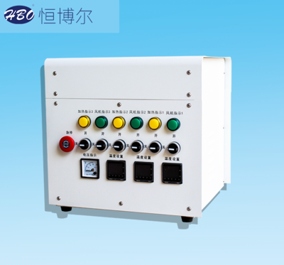
HBO's temperature-control-box offer is illustrated as a separate enclosure with an emergency-stop button, repeated heater/fan indicator and selector pairs, temperature displays and a voltage indicator. The official text gives a configurable temperature range of 0–350°C, an advertised ±1°C adjustment/control figure and 220 V or 380 V at 50 Hz. The parameter poster, however, specifies 220 V, 50 Hz for the illustrated box and dimensions written as 620×420×415 without a unit. The text and image therefore describe options and an illustrated example, not a single complete issued specification.
A control-box enquiry should identify which sensors and heater/fan circuits the ordered enclosure serves. The source states programmable temperature and an overheat device that cuts heater power above a preset temperature, but provides no inspected wiring diagram, switched-load rating, ingress class or independent protection architecture. This brief makes those integration decisions explicit instead of treating the words intelligent or ±1°C as a guaranteed process tolerance or a safety-system certification.
This is an equipment family; its range does not identify one orderable configuration.
Swipe the table, or focus it and use arrow keys, to read the conditions and sources.
| Parameter | Published value | Conditions and evidence |
|---|---|---|
| Published configurable temperature range | 0–350°C | Source setpoint/control statement, not a demonstrated process-product tolerance. Source |
| Advertised control figure | ±1°C | No inspected calibration, load response, measurement location or uncertainty basis. Source |
| Text versus illustrated supply | Text: 220 V or 380 V, 50 Hz; poster: 220 V, 50 Hz | Alternative configurations retained; confirm the ordered circuit supply. Source |
| Dimensions as printed | 620×420×415; unit not stated | No inferred millimetre unit or selected enclosure drawing. Source |
| Visible controls | Heater/fan pairs, temperature displays, voltage indication and emergency-stop button | Illustrated example; channel count/capacity not guaranteed for every order. Source |
| Described overheat action | Cut heater power above preset overheat temperature | Supplier description, not an inspected independent safety circuit or certification. Source |
| Integration gaps | Sensor type/channels, switched-load current, wiring, enclosure class and protocol | No assumed Modbus, IP rating, SIL or universal heater compatibility. Source |
List each heater and fan circuit with its required supply and load, and ask which circuits the quotation includes. Resolve the 220/380 V text against the 220 V illustrated poster using an ordered schematic and nameplate. Do not assume the controller supply and every switched load have the same voltage, phase or current requirement.
Request rated switched-load capacity, switching method, terminal schedule and protective-device coordination from the supplier. A front-panel photograph cannot establish internal conductor, contactor or semiconductor ratings. The dimensions remain as printed until a unit-bearing selected drawing is issued.
The source says LED display, key operation, programmable temperature and a 0–350°C setting range. Identify actual sensor type, number of channels, input configuration and sensor location for the selected process. The visible example has repeated temperature displays, but the source does not establish one universal channel count or sensor kit.
Ask for the actual programming functions, control method and any communication interface. Do not infer a ramp/soak program, logging or Modbus protocol from programmable or intelligent. The advertised ±1°C figure requires a specified calibration and response test before it can be used as a process acceptance tolerance.
The supplier text describes cutting heater power when a preset overheat threshold is exceeded. Request the issued design identifying the limiting sensor, switching path, reset behaviour and the relationship between routine control and protection. No independent high-limit architecture or certified safety performance is established by the reviewed webpage.
Agree fan/heater sequencing and the documented response to a fan trip, sensor fault, loss of airflow and power return for the selected installation. The emergency-stop button in the image is an observed front-panel component; its appearance alone does not prove the complete installed stopping function.
Specify the installation environment and ask for the selected enclosure's ingress class, permissible ambient conditions, heat dissipation, mounting arrangement and service access. None of those ratings is invented from a white enclosure photograph. Identify the sensors, wiring, connectors and accessories included.
Acceptance should demonstrate each agreed input/output channel, calibration/response at the defined point and the documented protection/sequence tests with the actual connected loads. Obtain an issued schematic, operating instructions and spare-parts scope. Current price, lead time, verified electromagnetic conformity and independent test results remain unknown.
A configurable temperature box with a published setpoint range and illustrated controls.
Read the source220/380 V text versus 220 V poster, and unlabelled dimension units are not silently fixed.
Read the sourceLoad/sensor schedule, issued circuit, protection sequence, installation ratings and acceptance records.
Read the sourceCompiled by HVACDeck Editorial. Source review identifies what the publication states; it is not an independent performance test or certification.
Editorial method and corrections · Report a detail with this page URL
Send the manufacturer your required duty, installation conditions and the unresolved items identified in this brief.
HBO wall-mounted fan heaters · Air distribution and mounting scope
HBO industrial heat guns · Air source and localized thermal duty
HBO hot-air ducts · Insulation, flexibility and connected limits
HBO air knives · Slot geometry, source pressure and drying acceptance
HBO circulating hot-air packages · Return-air temperature review
HBO portable 3–10 kW hot-air heaters · Supply and process selection