
Envicool in-row liquid-to-air CDU · Room heat-sink assessment
Evaluate the 120 kW cabinet claim alongside existing room cooling, coolant hydraulics and selected pump/fan fault states.
From Shenzhen Envicool Technology Co., Ltd.
Individual product research · HVACDeck Editorial · Sources checked 2026-10-11

Check the room-air heat sink before selecting the liquid-to-air cabinet
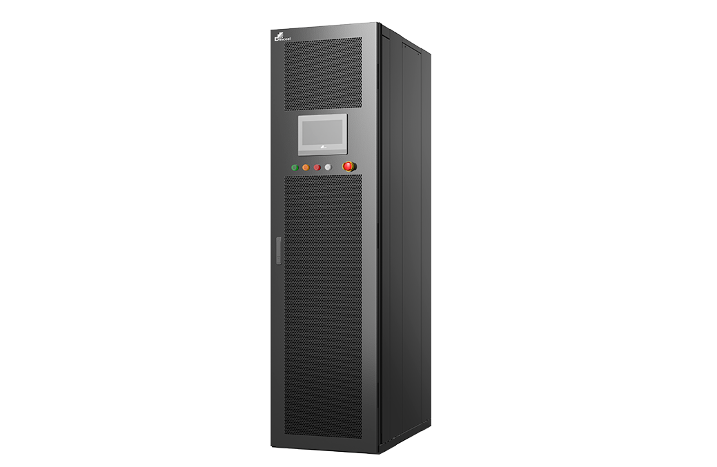
This Envicool in-row CDU transfers heat from liquid-cooled servers into the data-centre air. The official page describes a pumped coolant loop, a liquid-to-air exchanger, a rear-door fan, controller and pipes. Its single-cabinet heat-exchange capacity is stated as 120 kW, with two water pumps and N+1 hot-pluggable fans. The original product rendering shows a tall floor-standing cabinet with front controls; it does not establish an ordered layout or complete rating.
The absence of an external coolant supply does not remove the server heat from the building: the description explicitly uses the computer room's cold air as the heat sink. This makes the existing room-air system's spare capacity and airflow central to a retrofit assessment. The advertised total input below 5% of heat load has no inspected rating conditions or whole-room energy boundary. This brief separates CDU selection from the air-conditioning work needed to handle its discharged heat, without inventing coolant temperatures, pump head or selected footprint.
Published parameters and their scope
This is an equipment family; its range does not identify one orderable configuration.
- Family designation
- In-row liquid-to-air CDU
Swipe the table, or focus it and use arrow keys, to read the conditions and sources.
| Parameter | Published value | Conditions and evidence |
|---|---|---|
| Heat-transfer path | Server liquid loop to computer-room air | Official operating description; existing room cooling remains necessary. Source |
| Published cabinet heat exchange | 120 kW | Source value without inspected coolant/air rating conditions. Source |
| Pump arrangement | Two high-performance water pumps | No issued pump curve or guaranteed one-pump remaining duty. Source |
| Fan feature | N+1 hot-pluggable fans | Selected fan schedule and fault-state capacity required. Source |
| Input claim | Total power below 5% of heat load | Supplier claim without complete room-air energy boundary. Source |
| Deployment positioning | Existing hot/cold aisles; no external coolant supply or underfloor routing | Order-specific layout and site work still need definition. Source |
Selection and application review
Account for where the server heat actually goes
The stated circuit transfers server heat to the room air. Issue both the liquid-cooled server load and the existing room cooling/airflow assessment. Ask where warm discharge enters the aisle and how the room system will remove the added load without recirculation or unacceptable rack inlet conditions.
A waterless retrofit claim means no external coolant supply in the described arrangement; it does not mean no coolant inside the equipment or no external heat-rejection energy. The 120 kW cabinet figure should not be added to an already fully loaded air-conditioning system as if it created extra building cooling capacity.
Obtain a simultaneous air and coolant rating
Provide required server coolant supply/return temperatures, compatible fluid, flow and allowable pressure drop together with available room inlet-air conditions. Ask for selected thermal duty, exchanger approach, fan airflow and complete input at those simultaneous points. The public page does not issue those rating conditions.
Request pipe sizes, filtration/material compatibility, pump curves and control limits. Identify the server OEM's allowable pressure, fluid quality and temperature envelope. Two pumps in the feature list do not establish the head or full 120 kW capacity with one pump isolated.
Design aisle placement and service access
Obtain selected cabinet dimensions, weight, supports, heat-discharge direction and maintenance clearance. The product is positioned for existing cold/hot aisles, but the actual room layout must avoid air short-circuiting and preserve access to racks, pipe connections and controls.
Freeze which coolant connections and commissioning tasks are included. No underfloor routing requirement does not settle every hose route, overhead connection, support or leak-containment detail. The original illustration provides appearance only, not a site-ready dimensional plan.
Verify the ordered fan and pump resilience
Request fan N+1 operation and remaining heat transfer after a fan fault at the selected air/coolant point. For hot plugging, use the supplier's issued access and replacement procedure rather than assuming every component can be removed with unrestricted operation.
Document pump changeover, power supplies, control response and server protection on low flow or high coolant temperature. Confirm communication protocol names and register maps; the source's mainstream-protocol wording does not prove a specific interface. Agree leak/alarm handling using the actual selected circuit.
Compare complete retrofit energy and accept the duty
Ask which fans, pumps and controls are included in the below-5% input statement and obtain the conditions behind it. Add the room-air and ultimate heat-rejection loads separately when comparing retrofit options. CDU input alone is not site PUE or a whole-system saving.
Acceptance should verify coolant duty and quality, room-air effects, complete equipment input and the agreed fault states. Price, lead time and independent installed results remain unknown.
Check spare room capacity
Account for all server heat discharged to air and verify aisle airflow and cooling headroom.
Select both heat-transfer sides
Obtain coolant and air ratings, pump curves and ordered cabinet layout.
Accept the retrofit boundary
Measure liquid duty and room conditions, then verify controls and fault-state operation.
Sources and review scope
Compiled by HVACDeck Editorial. Source review identifies what the publication states; it is not an independent performance test or certification.
- Official in-row liquid-to-air CDUChecked 2026-10-11 · Complete operating description and original cabinet rendering read; 120 kW and input claim retained without fabricated rating conditions.
Editorial method and corrections · Report a detail with this page URL
Turn the evidence into an enquiry
Send the manufacturer your required duty, installation conditions and the unresolved items identified in this brief.
Other equipment from this manufacturer
Envicool MC power-container cooling · Heating, humidity and dry contacts
Envicool BattCool-AC container cooling · Air paths and standby control
Envicool BattCool-C / EMW chillers · Battery coolant and fault duty
Envicool EMA cabinet air conditioners · Air path and filter service
Envicool HC combo cabinet cooling · Heat-pipe and compressor modes
Envicool DC / EC outdoor cabinet cooling · Power and selected duty