
Rack/terminal boundary
Check heat captured, airflow, door support and remaining duty after terminal faults.
 HVAC & REFRIGERATION
Read the 5–15 kW rack positioning together with circuit scope, rack mechanics, terminal resilience and the separate heat-rejection energy boundary.
From Shenzhen Envicool Technology Co., Ltd.
Individual product research · HVACDeck Editorial · Sources checked 2026-10-11
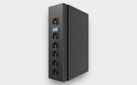
Envicool's rear-door heat exchanger is described as a heat-pipe cooling terminal mounted at the back of a rack. The official page positions one RDHx against a 5–15 kW rack and shows a rear-door assembly with multiple fans and a display. It describes redundant terminal fans, dual power supplies and optional dual refrigerant pumps. This is not presented here as a conventional chilled-water rear-door coil: the source explicitly calls the architecture a heat pipe.
The published single-terminal EER above 100 and terminal CLF of 0.018 are terminal claims, not complete facility efficiency. The 100% sensible-heat design and no-condensation/no-water wording require the selected circuit and actual environmental conditions to be checked; they do not establish immunity to every moisture scenario. This individually written brief addresses rack fit, air resistance, the remote heat-rejection boundary and continued cooling during service. No independent capacity or energy test was inspected.
This is an equipment family; its range does not identify one orderable configuration.
Swipe the table, or focus it and use arrow keys, to read the conditions and sources.
| Parameter | Published value | Conditions and evidence |
|---|---|---|
| Cooling architecture | Heat-pipe rear-door exchanger | Source description; not automatically a chilled-water coil. Source |
| Published rack positioning | One terminal for a 5–15 kW rack | No selected air/circuit conditions or ordered-model rating table. Source |
| Terminal arrangement | Rear-mounted, multiple fans and a display | Original rendering; actual rack compatibility and support loads not specified. Source |
| Resilience features | Redundant fans and dual power; optional dual refrigerant pumps | Order-specific failure-state scope required. Source |
| Terminal efficiency claims | EER >100; terminal CLF 0.018 | Supplier terminal boundary, not whole-system or facility efficiency. Source |
| Moisture statements | 100% SHR, no condensation water and no water in data centre | Selected circuit/temperatures/environment must substantiate the claim. Source |
| Service/layout options | Online service and hoistable plate exchanger described | Access, isolation and structural support require an issued design. Source |
Provide rack dimensions, exhaust layout, cable exits, server airflow and intended rack load. Request the selected rear-door drawing, hinge/support requirements, opening clearance, weight and maintenance access. A rear-mounted terminal may avoid occupying rack space while still requiring external clearance and a checked mechanical interface.
Obtain air resistance and terminal fan performance at the required server airflow. The 5–15 kW rack positioning is not an acceptance rating at every exhaust temperature or fan state. Agree which portion of rack heat must be captured and how remaining room heat will be handled.
Request a circuit schematic identifying the rear-door terminal, refrigerant, pump arrangements, plate exchanger and ultimate heat sink. Establish which equipment is in the quotation and which is supplied by the site. Do not substitute a generic water-coil drawing for the source's heat-pipe architecture.
The optional dual refrigerant pumps are not necessarily included. Obtain permissible pipe length/elevation, fluid charge, pressure and connection requirements from the selected designer. The website gives no numerical network limits or issued configuration, so this page supplies none.
Ask for the selected operating temperatures, permitted environmental conditions and the manufacturer's dew-point/control strategy. The source's 100% SHR and no-condensation wording describes intended operation; it is not an independently tested statement covering every installation, start-up or fault condition.
Clarify what the no-water-in-data-centre boundary includes and where any secondary water circuit or plate exchanger is located. Request leakage monitoring and the relevant emergency response for the actual fluids. No universal leak-free, condensation-free or material compatibility guarantee is inferred.
Agree remaining rack duty after a terminal fan fault, one power feed loss or the failure of an ordered pump. Identify shared components in the heat-rejection circuit that may limit redundancy. Dual feeds and multiple fans alone do not establish full cooling availability.
For online maintenance, request isolation points, replacement sequence, access and any temporary derating. A hoisted plate exchanger needs a documented support and service arrangement. The generic online-service statement is not permission to open a pressurised circuit or remove components without the manufacturer's procedure.
Request the air and refrigerant conditions and included electrical loads behind terminal EER above 100 and CLF 0.018. Keep those values separate from pumps, external heat rejection and the wider facility. Compare complete-system input using a matched load and climate boundary.
Acceptance should record rack heat captured, exhaust/return conditions, terminal and external input, air resistance and the agreed failure/service states. Current quotation, lead time and independent site performance remain unknown. This rear-door architecture is distinct from the in-row DX unit, so its page addresses different interfaces rather than repeating the same buying checklist.
Check heat captured, airflow, door support and remaining duty after terminal faults.
Specify refrigerant pumps, plate exchanger, external equipment and pipe limits.
Report terminal input separately from all external heat-rejection auxiliaries.
Compiled by HVACDeck Editorial. Source review identifies what the publication states; it is not an independent performance test or certification.
Editorial method and corrections · Report a detail with this page URL
Send the manufacturer your required duty, installation conditions and the unresolved items identified in this brief.
Envicool MC power-container cooling · Heating, humidity and dry contacts
Envicool BattCool-AC container cooling · Air paths and standby control
Envicool BattCool-C / EMW chillers · Battery coolant and fault duty
Envicool EMA cabinet air conditioners · Air path and filter service
Envicool HC combo cabinet cooling · Heat-pipe and compressor modes
Envicool DC / EC outdoor cabinet cooling · Power and selected duty