
Cling EDDR roof-mounted liquid battery cooling
Specify the glycol loop and selected pump before committing the roof envelope or interpreting auxiliary demand as full input.
From Zhengzhou Cling · Vehicle HVAC and thermal management
Individual product research · HVACDeck Editorial · Sources checked 2026-10-11

Separate battery-liquid selection from passenger-air cooling
Cling’s roof-mounted EDDR liquid thermal-management family is presented on separate capacity landing pages, but those pages repeat the same four-model schedule. One series brief therefore covers its 3, 5, 8 and 13 kW cooling choices. Unlike a passenger-air roof unit, the schedule specifies a 50% by-volume ethylene-glycol secondary circuit, optional internal pump and liquid connections. It supplies no rated coolant inlet/outlet temperatures, flow, pressure loss or battery heat-load test.
The roof table lists 600 V nominal high voltage and 24 V nominal low voltage. Its published body size is 1,300 × 290 × 56 mm across a merged cell, requiring a current selected-model drawing. Optional PTC heat is not standard heat-pump heating. Before approving a vehicle battery circuit, resolve coolant duty, pump responsibility, electrical consumption boundaries and the unusual common outline with the supplier and vehicle integrator.
Published parameters and their scope
This is an equipment family; its range does not identify one orderable configuration.
- Family designation
- EDDR-01 / 02 / 03 / 04
Swipe the table, or focus it and use arrow keys, to read the conditions and sources.
| Parameter | Published value | Conditions and evidence |
|---|---|---|
| Four cooling choices | EDDR-01/02/03/04: 3/5/8/13 kW | No rated coolant temperatures, flow or ambient duty point supplied. Source |
| Two voltage circuits | High 600 V nominal (400–750 V DC); low 24 V nominal (18–32 V DC) | Actual connectors, protection, startup and DC-DC allocation require an order drawing. Source |
| Published auxiliary row | 300/300/600/900 W under an ambiguous low/high-voltage-demand heading | Not defined as compressor input or whole-unit consumption; efficiency 2.2 has no documented test basis. Source |
| Liquid and pump | 50% V/V ethylene-glycol solution; internal pump optional | Compatibility, inhibitor, pressure/head and selected-pump duties remain unknown. Source |
| Roof drawing question | Merged outline 1,300 × 290 × 56 mm; Φ25 connections/custom alternatives | Keep 56 mm as a source question; do not add a zero or reuse another family drawing. Source |
| Environmental and heating claims | IPX7; cooling operation −20°C to +60°C; optional PTC 5/10/14/24 kW | No dust-protection digit, full-range capacity map or PTC-to-model selection table reviewed. Source |
Selection and application review
Calculate battery-liquid duty at actual vehicle conditions
Provide battery heat rejection through charging, driving and stationary modes, target coolant temperatures and permitted fluid limits. Obtain conditioned capacity with glycol concentration, flow and ambient explicitly stated. A 3–13 kW series row cannot establish performance at an unspecified inlet temperature.
The advertised −20°C to +60°C range describes cooling operation, not a guarantee of nominal duty at both extremes. Request startup, freeze protection and derating logic. The unqualified efficiency value 2.2 does not support a platform COP or energy-consumption comparison.
Assign pump, expansion and liquid-circuit ownership
The source marks the internal pump optional. Define whether circulation comes from the unit or vehicle, and request the pump curve at the chosen glycol temperature/concentration, available head and control requirements. Pump inclusion is a purchase decision, not an assumed standard component.
Close expansion, fill/vent, drainage, filtration and fluid/material compatibility through an issued circuit diagram. Φ25 and a flange/copper-head option do not define the complete vehicle connection. Approve the coolant formulation and service procedure without inventing a corrosion or freeze rating.
Resolve the roof outline before body manufacture
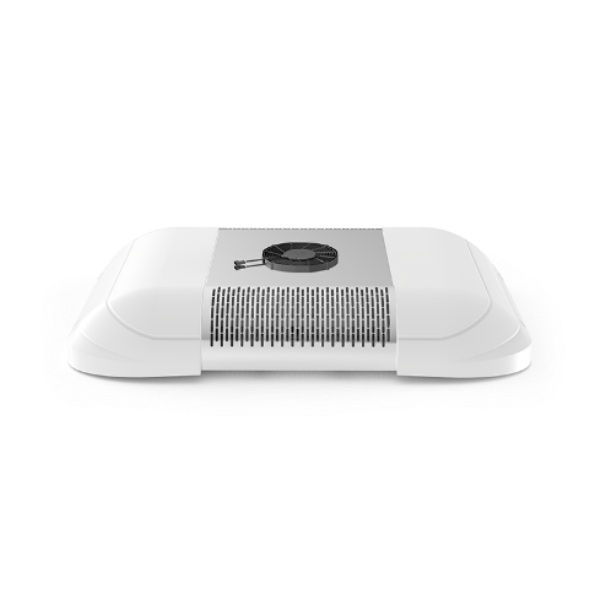
The common table prints 1,300 × 290 × 56 mm without separate model outlines. Request the current drawing for the actual order, including mounts, connection projections, airflow openings and removal access. The original roof photograph establishes appearance rather than dimension accuracy.
Approve roof structure and heat-rejection air paths with the body builder. IPX7 is a supplier statement about water protection; it supplies no dust digit and no reviewed test report. Require the actual model’s environmental evidence for the installation instead of rewriting it as IP67.
Close two-voltage power and optional heating separately
Obtain high- and low-voltage input schedules, operating/start limits, isolation/protection interfaces and connector pinouts. The ambiguous demand row must not be published as total electrical power. Define whether the unit or vehicle supplies low-voltage conversion.
PTC 5/10/14/24 kW is listed as optional, without mapping to each cooling model. Select heater power, switching and interlocks against the liquid circuit and vehicle power budget. This source does not establish native refrigerant heat-pump heating. R134a/R1234yf denotes configuration alternatives, not a refrigerant blend.
Approve communications and an installed liquid-system test
Request the actual CAN specification, identifiers, update rate, fault codes and fail-safe behaviour. Self-diagnosis wording and an EMC level III statement supply no protocol file or standard/report scope. Agree commissioning responsibilities with the vehicle controller team.
Accept the selected unit using conditioned cooling, coolant flow/pressure, input, leak protection, CAN faults and optional heating tests at agreed modes. Current price, lead time and independently verified environmental performance remain unknown. Repeated capacity pages are consolidated into this single individually researched application brief.
Select conditioned liquid duty
Approve coolant temperatures, concentration, flow and ambient.
Freeze interfaces
Resolve pump, current roof drawing, two-voltage input and CAN.
Test the ordered options
Verify circulation, cooling, faults and separately selected PTC heating.
Sources and review scope
Compiled by HVACDeck Editorial. Source review identifies what the publication states; it is not an independent performance test or certification.
- Official roof liquid-cooling seriesChecked 2026-10-11 · Complete four-model repeated schedule and configuration/update warning read; ambiguous power and outline retained.
- Official 8 kW capacity landing pageChecked 2026-10-11 · Read as repeated series evidence; not used to create another capacity URL.
- Official 13 kW capacity landing pageChecked 2026-10-11 · Read as repeated series evidence; no independent model duty conditions found.
- Original roof family photographChecked 2026-10-11 · Original image visually inspected; does not verify the unusual common outline or exact pump option.

Editorial method and corrections · Report a detail with this page URL
Turn the evidence into an enquiry
Send the manufacturer your required duty, installation conditions and the unresolved items identified in this brief.
Continue the selection
Other equipment from this manufacturer
Cling EFDR independent glycol cooling
Cling DFDD independent-drive vehicle cooling
Cling FFND/XFND internal bus cooling
Cling GZHD/EZHS rear-mounted bus HVAC