
Cling FFND/XFND internal bus cooling
Approve separate condenser/evaporator packages and zone air paths; one unusual dimension requires a current issued correction or confirmation.
From Zhengzhou Cling · Vehicle HVAC and thermal management
Individual product research · HVACDeck Editorial · Sources checked 2026-10-11

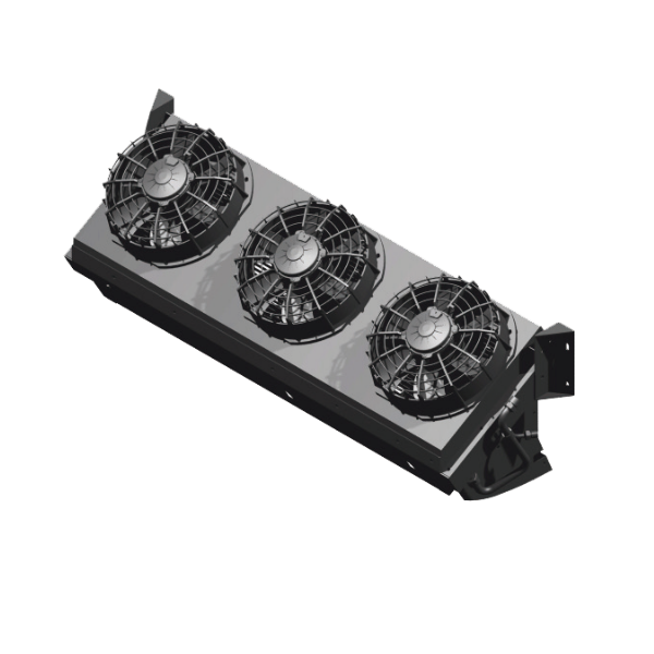
Package internal exchangers around chassis and passenger zones
Cling’s internal FFND/XFND family lists separate condenser and evaporator dimensions for commercial, school, high-chassis and double-deck applications. That split makes the vehicle packaging task different from selecting a single roof box. The source describes microchannel exchange, zone temperature control and ABS construction, but does not provide a complete refrigerant piping drawing, installed static-pressure schedule or an approved vehicle-zone control file.
FFND-08 lists 56 kW R134a cooling and separate upper/lower evaporator flows of 6,000/3,000 m³/h, with separate upper/lower body sizes. A smaller XFND-10 condenser dimension is printed as 588 × 20 × 702 mm; the 20 mm value is unresolved and must not be silently expanded. Confirm the actual assemblies, refrigerant lines and access with issued drawings before the body builder freezes internal compartments and ceilings.
Published parameters and their scope
This is an equipment family; its range does not identify one orderable configuration.
- Family designation
- FFND / XFND
Swipe the table, or focus it and use arrow keys, to read the conditions and sources.
| Parameter | Published value | Conditions and evidence |
|---|---|---|
| FFND-08 thermal/air rows | 56 kW; R134a; upper/lower evaporator flow 6,000/3,000 m³/h | Shared footnote indoor 40°C/outdoor 35°C; humidity/drive speed unprovided. Source |
| FFND-08 evaporator bodies | Upper 1,468 × 387 × 202 mm; lower 1,510 × 586 × 261 mm | Separate source assemblies; no complete installed support/duct envelope. Source |
| FFND-06 condenser choices | Side 855 × 476 × 1,085 mm; rear 1,951 × 372 × 443 mm | Choice/drawing needs supplier confirmation; not two additional product pages. Source |
| XFND-10 source question | Condenser 588 × 20 × 702 mm | 20 mm entry retained as unresolved; no inferred correction to 200 or another size. Source |
| Compressor references | FFND-08 750 cc; FFND-06 650 cc; all rows R134a | Actual model, drive and line-selection requirements not documented. Source |
| Missing integrated schedule | No refrigerant line lengths/charge, input/current or complete control/pressure map reviewed | Zone-control and microchannel statements are features, not an issued integration file. Source |
Selection and application review
Approve the separate machine locations and refrigerant circuit
Identify each condenser and evaporator location against the actual high-chassis, school or double-deck body. Obtain the selected arrangement’s supports, openings, air paths and service projections. Do not use one shipping outline as the envelope of a distributed vehicle system.
Request allowable refrigerant routing, pressure losses, line lengths/elevations, charge and installation instructions. The reviewed table does not provide them. Close the actual compressor drive and the responsibility for field connections, evacuation/leak checks and commissioning without inventing limits from another family.
Balance passenger zones against duct resistance
For FFND-08, use the stated 6,000/3,000 m³/h upper/lower rows as source references and obtain delivered-flow selections for the actual ducts and grilles. The two zones have different body sizes and loads; they cannot be approved by dividing total capacity equally without evidence.
Define return air, zone sensors, control setpoints and occupancy/door-cycle modes. The feature ‘zone temperature control’ supplies no sequence or independent balanced result. Request the controller configuration, actuator/sensor scope and cabin-zone acceptance criteria.
Resolve dimensions and body-builder access before manufacture
The FFND-06 source lists side and rear condenser sizes, while XFND-10 includes a questionable 20 mm dimension. Obtain current assembly drawings and a written confirmation of the selected arrangement. Preserve the original ambiguity rather than guessing a zero was omitted.
Reserve filter, fan, coil and refrigerant service space at each internal location. Confirm removal routes and condensate drainage around permanent interior finishes. A compact internal coil can become unserviceable if support panels and ceiling routes are closed before drawings are approved.
Select drive, power and acoustic requirements with the vehicle
Request the actual compressor model/speed map, electrical supply and fan/control demand. The table provides displacement and air quantities but no complete energy schedule. Microchannel or ABS construction does not establish a COP, weight reduction or all-vehicle fuel saving.
Obtain sound/vibration evidence and the required component/model conformity file. Explain what the selected controller includes and how it interacts with the vehicle. The platform has not verified an internal-assembly approval, passenger comfort test or the pictured component’s exact complete-system role.
Test the distributed assembly at defined vehicle conditions
Provide cabin/zone loads, climate, chassis and compartment drawings, drivetrain/power data and maintenance constraints. Obtain a current selected condenser/evaporator combination, refrigerant and control drawings and a conditioned thermal/air/input schedule. Resolve the 20 mm source entry before dimensional approval.
Acceptance should verify zone delivery, refrigerant integrity, drainage, controls and service access at agreed idle/driving modes. Current price, stock, delivery and independent internal-system performance remain unknown. The family is kept in one structured brief with separate configuration decisions.
Select actual locations
Approve condenser/evaporator combination and current dimensions.
Close zones and piping
Obtain duct/flow, refrigerant and control interfaces.
Verify the installed assembly
Test delivery, leak/drain functions and service access.
Sources and review scope
Compiled by HVACDeck Editorial. Source review identifies what the publication states; it is not an independent performance test or certification.
- Official internal-family pageChecked 2026-10-11 · Complete four-model table, separate exchanger dimensions, zoning statements and warning read; unusual dimension retained.
- Original internal-family component imageChecked 2026-10-11 · Original fan/exchanger assembly image visually inspected; exact model and complete vehicle circuit unverified.

Editorial method and corrections · Report a detail with this page URL
Turn the evidence into an enquiry
Send the manufacturer your required duty, installation conditions and the unresolved items identified in this brief.
Continue the selection
Other equipment from this manufacturer
Cling EFDR independent glycol cooling
Cling EDDR roof-mounted liquid battery cooling
Cling DFDD independent-drive vehicle cooling
Cling GZHD/EZHS rear-mounted bus HVAC